Ford Fiesta: Front Drive Halfshafts / Inner Constant Velocity (CV) Joint Boot. Removal and Installation
Ford Fiesta 2014 - 2019 Service Manual / Driveline / Front Drive Halfshafts / Inner Constant Velocity (CV) Joint Boot. Removal and Installation
Special Tool(s) / General Equipment
 |
205-343
(T95P-3514-A)
Installer, Constant Velocity Joint Boot Clamp TKIT-1995-F TKIT-1995-FM/FLM TKIT-1995-LM/M |
| Flat Headed Screw Driver | |
| Puller | |
| Bearing Separator | |
| Vise | |
Materials
| Name | Specification |
|---|---|
| Motorcraft® Constant Velocity Joint Grease XG-5 |
WSS-M1C258-A1 |
Removal
-
Remove the front halfshaft.
Refer to: Front Halfshaft LH (205-04 Front Drive Halfshafts, Removal and Installation).
Refer to: Front Halfshaft RH (205-04 Front Drive Halfshafts, Removal and Installation).
-
-
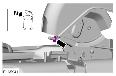
Remove and discard the large and small CV boot clamps.
-
Position the CV joint boot and the remove the inner CV joint housing.
-
Remove and discard the large and small CV boot clamps.
 |
-
-
Remove and discard the CV joint tripod bearing circlip.
-
Using the bearing seperator and bearing puller remove the CV tripod.
Use the General Equipment: Puller
Use the General Equipment: Bearing Separator
-
Remove the inner CV joint boot.
-
Remove and discard the CV joint tripod bearing circlip.
 |
Installation
-
Using boot clamp pliers, install the small CV boot clamp and the inner CV joint boot.
Use Special Service Tool: 205-343 (T95P-3514-A) Installer, Constant Velocity Joint Boot Clamp.
 |
-
NOTE: Make sure that a new component is installed.
Using a vise, install the CV joint tripod bearing.
Use the General Equipment: Vise
 |
-
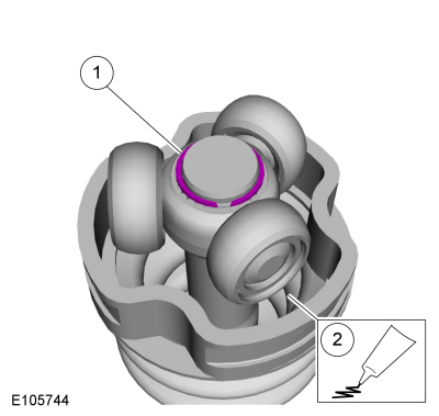
NOTE: Grease sachet is supplied with boot kit.
-
Install the new CV joint tripod bearing circlip.
-
Install the grease sachet evenly in the CV joint case.
Material: Motorcraft® Constant Velocity Joint Grease / XG-5 (WSS-M1C258-A1)
-
Install the new CV joint tripod bearing circlip.
 |
-
-
Install the grease sachet evenly in the CV joint boot and the CV joint housing.
Material: Motorcraft® Constant Velocity Joint Grease / XG-5 (WSS-M1C258-A1)
-
Position the CV joint boot and the CV joint housing.
-
Install the grease sachet evenly in the CV joint boot and the CV joint housing.
 |
-
-
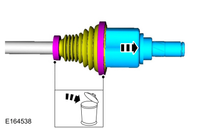
Insert the intemediate shaft into the CV boot. Use a flat blade screw driver to release trapped air.
Use the General Equipment: Flat Headed Screw Driver
-
Completely slide the intermediate shaft into the CV tripod housing until it bottoms out.
-
Slide the intermediate shaft out 25mm (1 inch).
-
Remove the flat blade screw driver.
Use the General Equipment: Flat Headed Screw Driver
-
Insert the intemediate shaft into the CV boot. Use a flat blade screw driver to release trapped air.
 |
-
Using the special tool, position back the CV boot and install the new large halfshaft boot clamp.
Use Special Service Tool: 205-343 (T95P-3514-A) Installer, Constant Velocity Joint Boot Clamp.
 |
-
Install the front halfshaft.
Refer to: Front Halfshaft LH (205-04 Front Drive Halfshafts, Removal and Installation).
Refer to: Front Halfshaft RH (205-04 Front Drive Halfshafts, Removal and Installation).
 Front Halfshaft RH. Removal and Installation
Special Tool(s) /
General Equipment
204-161
(T97P-1175-A)
Installer, HalfshaftTKIT-1997-LM2TKIT-1997-F/FM2TKIT-1997-FLM2
205-D070
(D93P-1175-B)
Remover, Front Wheel Hub
Removal
NOTICE:
Suspension fasteners are critical parts because they affect
performance of vital components and systems and their failure may result
in major service expense...
 Outer Constant Velocity (CV) Joint Boot. Removal and Installation
Special Tool(s) /
General Equipment
205-343
(T95P-3514-A)
Installer, Constant Velocity Joint Boot ClampTKIT-1995-FTKIT-1995-FM/FLMTKIT-1995-LM/M
Materials
Name
Specification
Motorcraft® Constant Velocity Joint GreaseXG-5
WSS-M1C258-A1
Removal
Remove the inner CV joint boot...
Other information:
Ford Fiesta 2014 - 2019 Service Manual: Rear View Mirrors - System Operation and Component Description. Description and Operation
System Operation Rear View Mirrors - Exterior, Power The LH and RH exterior mirror glass movement is controlled by the exterior mirror control switch and the LH and RH exterior mirror motors. The exterior mirror control switch receives voltage at all times from the CJB ...
Ford Fiesta 2014 - 2019 Service Manual: Instrument Panel Upper Section. Removal and Installation
Special Tool(s) / General Equipment Interior Trim Remover Removal All vehicles NOTE: Removal steps in this procedure may contain installation details. Remove the driver knee airbag. Refer to: Driver Knee Airbag (501-20B Supplemental Restraint System, Removal and Installation)...
Categories
- Manuals Home
- Ford Fiesta Service Manual (2014 - 2019)
- Engine
- Fuel Rail. Removal and Installation
- Engine. Assembly
- Engine System - General Information
- Camshafts. Removal and Installation
Parking Brake Control. Removal and Installation
Removal
NOTE: Removal steps in this procedure may contain installation details.
Remove the floor console.Refer to: Floor Console (501-12 Instrument Panel and Console, Removal and Installation).
Remove the driver seat.
Refer to: Front Seat (501-10 Seating, Removal and Installation).
Remove the parking brake cable adjustment lock nut.
 Loosen the parking brake cable adjustment nut.
Copyright © 2025 www.fofiesta7.com