Ford Fiesta: Fuel Charging and Controls - 1.6L EcoBoost (132kW/180PS) – Sigma / Fuel Rail. Removal and Installation
Special Tool(s) / General Equipment
 |
303-1567 Sizer, Teflon Seal TKIT-2010C-FLM |
 |
307-005
(T59L-100-B)
Slide Hammer |
 |
310-205 Fuel Injector Brush |
 |
310-206 Remover, Fuel Injector TKIT-2009A-FLM |
 |
310-207 Installer, Fuel Injector Seal Assembly TKIT-2009A-FLM |
Materials
| Name | Specification |
|---|---|
| Engine Oil - SAE 5W-20 - Synthetic Blend Motor Oil XO-5W20-Q1SP |
WSS-M2C945-B1 |
Removal
 WARNING:
Clean all fuel residue from the engine compartment. If not
removed, fuel residue may ignite when the engine is returned to
operation. Failure to follow this instruction may result in serious
personal injury.
 WARNING:
Do not work on the fuel system until the pressure has been
released and the engine has cooled. Fuel in the high-pressure fuel
system is hot and under very high pressure. High-pressure fuel may cause
cuts and contact with hot fuel may cause burns. Failure to follow these
instructions may result in serious personal injury.
-
Release the fuel system pressure.
Refer to: Fuel System Pressure Release (310-00B Fuel System - General Information - 1.6L EcoBoost (132kW/180PS) – Sigma, General Procedures).
-
Disconnect the battery.
Refer to: Battery Disconnect and Connect (414-01 Battery, Mounting and Cables, General Procedures).
-
Remove the ignition coil-on-plugs.
Refer to: Ignition Coil-On-Plug (303-07B Engine Ignition - 1.6L EcoBoost (132kW/180PS) – Sigma, Removal and Installation).
-
Remove the air cleaner outlet pipe.
Refer to: Air Cleaner Outlet Pipe (303-12B Intake Air Distribution and Filtering - 1.6L EcoBoost (132kW/180PS) – Sigma, Removal and Installation).
-
-
Disconnect the crankcase ventilation tube quick
release coupling. Release the hose retainer, release the clamp and then
remove the crankcase ventilation tube.
Refer to: Quick Release Coupling (310-00B Fuel System - General Information - 1.6L EcoBoost (132kW/180PS) – Sigma, General Procedures).
-
Remove the TC air inlet pipe retaining nut, the ball stud and loosen
the TC air inlet pipe clamp, then remove the TC inlet pipe.
Torque: 44 lb.in (5 Nm)
-
Disconnect the crankcase ventilation tube quick
release coupling. Release the hose retainer, release the clamp and then
remove the crankcase ventilation tube.
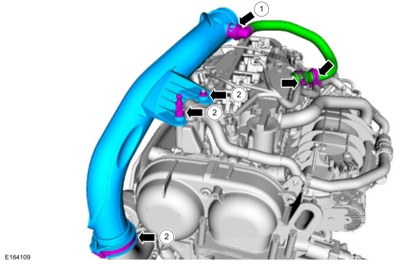 |
-
NOTE: When removing or installing the fuel injection pump noise insulator, spreading the openings will reduce the risk of damage.
Remove the high-pressure fuel pump noise insulator.
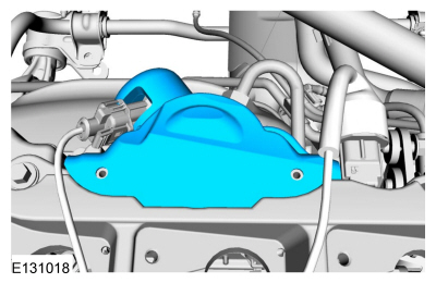 |
-
-
Release the wiring harness retainers. Disconnect the FRP sensor
electrical connector, the fuel injection pump electrical connector and
the CMP electrical connector. Position the wiring harness aside.
-
Remove the ignition coil-on-plug mounting bracket
retaining nut. Loosen the captured remaining ignition coil-on-plug
mounting bracket retainers and then remove the ignition coil-on-plug
mounting bracket.
-
Release the wiring harness retainers. Disconnect the FRP sensor
electrical connector, the fuel injection pump electrical connector and
the CMP electrical connector. Position the wiring harness aside.
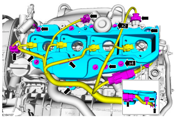 |
-
Remove the ignition coil-on-plug mounting bracket insulator.
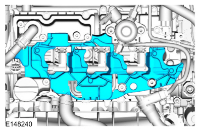 |
-
NOTICE: To release the fuel pressure in the high-pressure fuel tube, wrap the fuel injection pump flare nut with a shop towel to absorb any residual fuel pressure during the loosening of high-pressure fuel pump flare nut.
Disconnect the high-pressure fuel tube flare nuts. Remove and discard the high-pressure fuel tube.
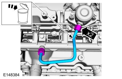 |
-
Disconnect the fuel injector electrical connectors.
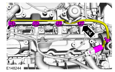 |
-
NOTICE: Pull out the fuel rails in the direction of the fuel injector axis or damage may occur to the fuel injectors.
NOTE: Use compressed air and remove any dirt or foreign material from the cylinder head, the engine block and the general surrounding area of the fuel rail and the fuel injectors.
NOTE: When removing the fuel rails, the fuel injectors may remain in the cylinder head and require the use of a Fuel Injector Remover tool to extract.
Remove the fuel rail bolts, then remove the fuel rail.
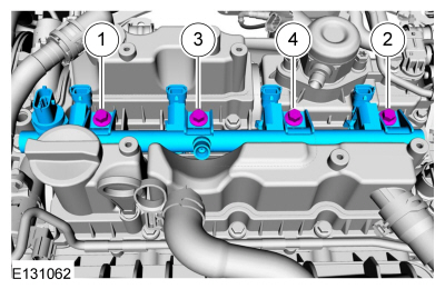 |
-
Remove the fuel injectors from the fuel rail.
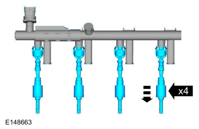 |
-
Remove and discard the fuel injector clips.
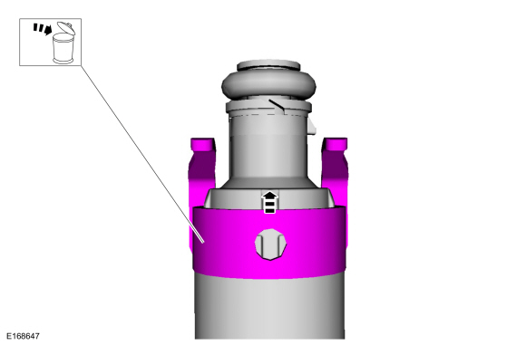 |
-
NOTICE: Use minimal force to remove the fuel injectors that remained in the cylinder head with the Fuel Injector Remover tool or damage to the fuel injector assembly may occur. Wiggling the injector by hand to break it loose may allow the injector to be removed by hand.
-
Using the special tools, remove any of the fuel injectors that remained in the cylinder head.
Use Special Service Tool: 307-005 (T59L-100-B) Slide Hammer. , 310-206 Remover, Fuel Injector.
-
Using the special tools, remove any of the fuel injectors that remained in the cylinder head.
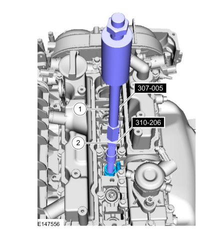 |
-
NOTE: Make sure to thoroughly clean any residual fuel or foreign material from the cylinder head, the engine block and the general surrounding area of the fuel rails and the fuel injectors.
NOTE: Do not use compressed air to clean the tip of the fuel injector.
NOTE: Do not use a brush to clean the tip of the fuel injector.
Using the special tool, clean the engine cylinder head fuel injector bores.
Use Special Service Tool: 310-205 Fuel Injector Brush.
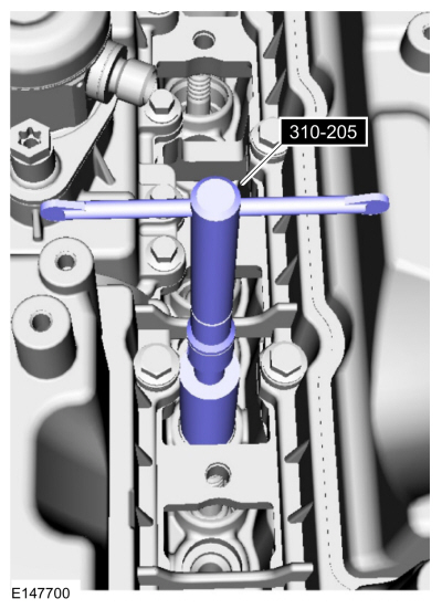 |
Installation
-
NOTE: Note the correct orientation of the fuel injector support rings for correct installation of the new fuel injector support rings.
Remove and discard the fuel injector O-rings. Remove and discard the fuel injector support rings.
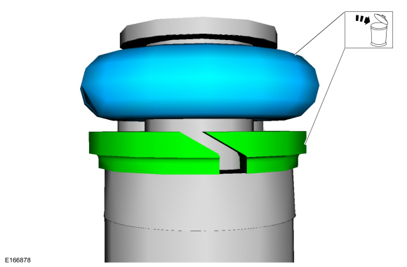 |
-
NOTICE: Use care when removing the lower Teflon® seals, not to scratch, nick or gouge the fuel injectors.
NOTICE: Do not attempt to cut the lower Teflon® seal without first pulling it away from the fuel injector or damage to the injector may occur.
-
Pull the lower Teflon® seal away from the injector.
-
Carefully cut and discard the lower fuel injector Teflon® seals.
-
Pull the lower Teflon® seal away from the injector.
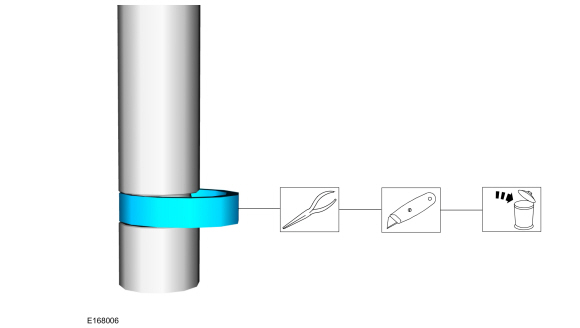 |
-
NOTICE: Do not lubricate the new lower Teflon® fuel injector seals.
-
Install the Arbor onto the fuel injector tips.
Use Special Service Tool: 310-207 Installer, Fuel Injector Seal Assembly.
-
NOTICE: Once the Teflon® seal is installed on the Teflon® Seal Guide, it should immediately be installed onto the fuel injector to avoid excessive expansion of the Teflon® seal.
NOTE: Make sure that new lower fuel injector Teflon® seals are installed.
Install the new Teflon® seals onto the Arbor, using the Pusher Tool slide the Teflon® seals along the Arbor.
-
Using the Pusher Tool, slide the Teflon® seals off
of the Teflon® Seal Guide and into the groove on the fuel injectors.
Use Special Service Tool: 310-207 Installer, Fuel Injector Seal Assembly.
-
Install the Arbor onto the fuel injector tips.
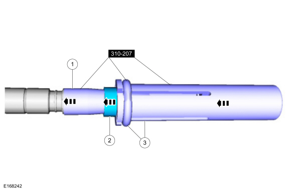 |
-
NOTE: Make sure the Teflon® seal is fully seated in the groove on the fuel injector before sizing the Teflon® seal.
-
Massage and warm the Teflon® seal with your fingers
before the Teflon® seal sizer tool is installed. This will aid in
installing the Teflon® seal sizer tool.
-
Position the Teflon® seal sizer tool with the larger
opening towards the Teflon® seal. Push while turning the Teflon® seal
sizer tool 180 degrees.
Use Special Service Tool: 303-1567 Sizer, Teflon Seal.
-
Once the Teflon® seal sizer tool is installed, check
and make sure the Teflon® seal is in the sizing portion of the Teflon®
seal sizer tool.
-
After one minute, turn the Teflon® seal sizer tool back 180 degrees and remove the Teflon® seal sizer tool .
-
Massage and warm the Teflon® seal with your fingers
before the Teflon® seal sizer tool is installed. This will aid in
installing the Teflon® seal sizer tool.
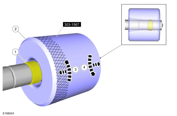 |
-
NOTICE: Use fuel injector O-ring seals that are made of special fuel-resistant material. The use of ordinary O-ring seals may cause the fuel system to leak. Do not reuse the O-ring seals.
NOTICE: Do not lubricate the new lower Teflon® fuel injector seals.
NOTICE: The new the fuel injector support rings must be installed in the correct orientation with the wide surface area facing up against the fuel injector O-ring seals. Improperly installed support rings may cause the fuel system to leak.
-
Install the new the fuel injector support rings.
-
Install the new fuel injector O-rings and lubricate with clean engine oil.
Material: Engine Oil - SAE 5W-20 - Synthetic Blend Motor Oil / XO-5W20-Q1SP (WSS-M2C945-B1)
-
Install the new the fuel injector clips.
-
Install the new the fuel injector support rings.
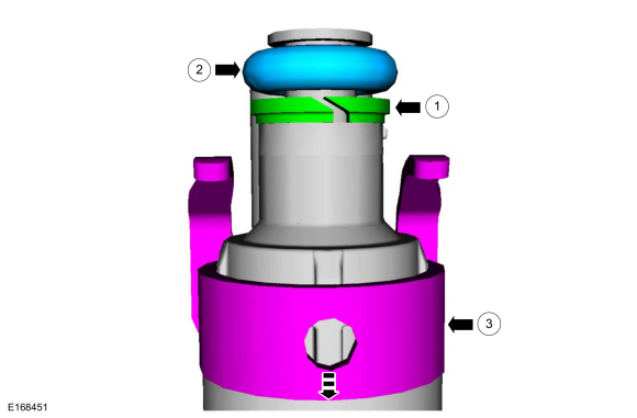 |
-
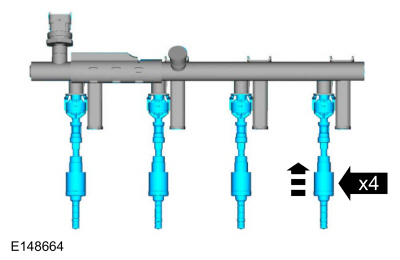
NOTICE: The FRP sensor must be replaced if it is removed from the fuel rail.
Install the fuel injectors to the fuel rail.
Refer to: Fuel Rail Pressure (FRP) Sensor (303-14B Electronic Engine Controls - 1.6L EcoBoost (132kW/180PS) – Sigma, Removal and Installation).
 |
-
NOTICE: Do not lubricate the new lower Teflon® fuel injector seals.
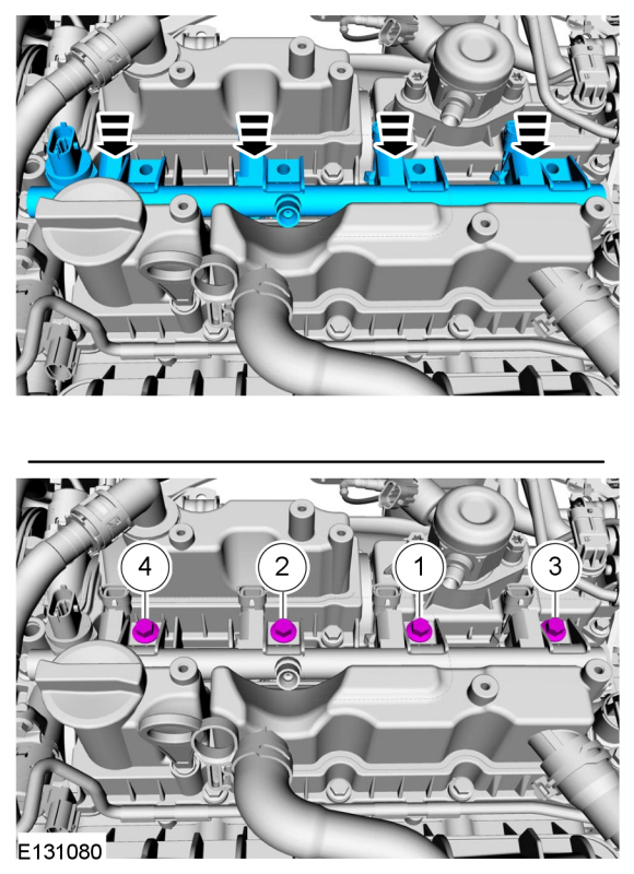
NOTE: Only tighten the 4 fuel rail bolts finger tight at this stage.
Install the fuel rail, push down on the fuel rail above the fuel injectors. Install and tighten the fuel rail bolts in the following 2 stages and in the sequence shown.
Torque:
Stage 1: 44 lb.in (5 Nm)
Stage 2: 17 lb.ft (23 Nm)
 |
-
Connect the fuel injector electrical connectors.
 |
-
-
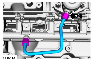
NOTE: Only tighten the 2 high pressure fuel tube flare nuts finger tight at this stage.
Make sure that a new high pressure fuel tube is installed. Calculate the correct torque wrench setting for the following torque using the Torque Wrench Adapter Formulas. Install the new high-pressure fuel tube, then tighten the high-pressure fuel tube flare nuts in the following 3 stages.
Torque:
Stage 1: 15 lb.ft (21 Nm)
Stage 2: Wait 5min
Stage 3: 15 lb.ft (21 Nm)
-
 |
-
Install the ignition coil-on-plug mounting bracket insulator.
 |
-
-
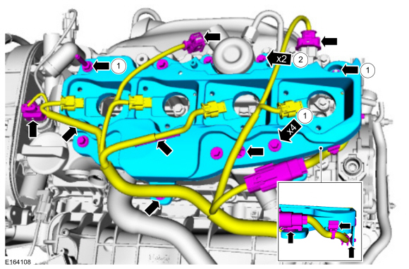
Install the ignition coil-on-plug mounting bracket,
then install and tighten the ignition coil-on-plug mounting bracket
retainers.
Torque: 89 lb.in (10 Nm)
-
Install and tighten the ignition coil-on-plug mounting bracket retainers.
Torque: 53 lb.in (6 Nm)
-
Install the wiring harness, then attach the wiring harness retainers.
Connect the FRP sensor electrical connector, the fuel injection pump
electrical connector and the CMP electrical connector.
-
Install the ignition coil-on-plug mounting bracket,
then install and tighten the ignition coil-on-plug mounting bracket
retainers.
 |
-
NOTE: When removing or installing the fuel injection pump noise insulator, spreading the openings will reduce the risk of damage.
Install the high-pressure fuel pump noise insulator.
 |
-
-
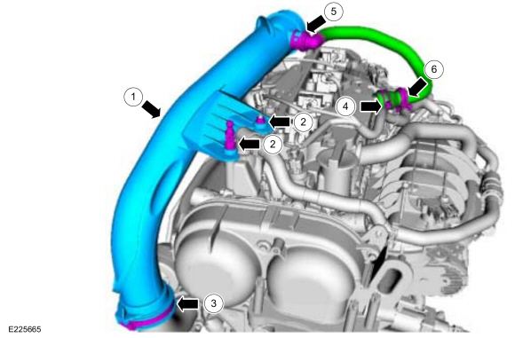
Install the TC inlet pipe.
-
Install and tighten the TC inlet pipe ball stud and retaining nut.
Torque: 44 lb.in (5 Nm)
-
Tighten the TC inlet tube clamp.
Torque: 44 lb.in (5 Nm)
-
Install the crankcase ventilation tube and clamp.
-
Connect the crankcase ventilation tube quick release coupling.
Refer to: Quick Release Coupling (310-00B Fuel System - General Information - 1.6L EcoBoost (132kW/180PS) – Sigma, General Procedures).
-
Attach the hose retainer.
-
Install the TC inlet pipe.
 |
-
Install the air cleaner outlet pipe.
Refer to: Air Cleaner Outlet Pipe (303-12B Intake Air Distribution and Filtering - 1.6L EcoBoost (132kW/180PS) – Sigma, Removal and Installation).
-
Install the ignition coil-on-plug.
Refer to: Ignition Coil-On-Plug (303-07B Engine Ignition - 1.6L EcoBoost (132kW/180PS) – Sigma, Removal and Installation).
-
Connect the battery.
Refer to: Battery Disconnect and Connect (414-01 Battery, Mounting and Cables, General Procedures).
-
Pressurize the fuel system.
Refer to: Fuel System Pressure Release (310-00B Fuel System - General Information - 1.6L EcoBoost (132kW/180PS) – Sigma, General Procedures).
 Fuel Pump Driver Module (FPDM). Removal and Installation
Removal
NOTE:
The FPDM is
located under the carpet and under left front seat attached to the rear
of the front cross floor support in front of the left front seat...
 Throttle Body. Removal and Installation
Removal
NOTE:
Removal steps in this procedure may contain installation details.
Refer to: Jacking and Lifting - Overview (100-02 Jacking and Lifting, Description and Operation)...
Other information:
Ford Fiesta 2014 - 2019 Service Manual: Pinpoint Test - DTC: I. Diagnosis and Testing
B007F:11, B007F:12, B007F:13 and B007F:1A Refer to Wiring Diagrams Cell 46 for schematic and connector information. Normal Operation and Fault Conditions The RCM continuously monitors the passenger safety belt retractor pretensioner circuits for the following faults: Resistance out of range Unexpected voltage Short to ground Faulted passe..
Ford Fiesta 2014 - 2019 Service Manual: Body Control Module (BCM). Removal and Installation
Removal NOTE: Removal steps in this procedure may contain installation details. NOTE: This step is only necessary when installing a new component. NOTE: The PMI process must begin with the current BCM installed. If the current BCM does not respond to the diagnostic scan tool, the tool may prompt for As-Built Data as part of the repair. A minimum of 2 RKE transm..
Categories
- Manuals Home
- Ford Fiesta Service Manual (2014 - 2019)
- Timing Belt. Removal and Installation
- Engine
- Camshafts. Removal and Installation
- Front Subframe. Removal and Installation
- Fuel Rail. Removal and Installation
Wheels and Tires. Diagnosis and Testing
Preliminary Inspection
Verify the customer concern by carrying out a road test on a smooth road. If any vibrations are apparent, Refer to the Symptom Chart: NVH.To maximize tire performance, inspect for signs of incorrect inflation and uneven wear, which may indicate a need for balancing, rotation or front suspension alignment.
Correct tire pressure and driving techniques have an important influence on tire life. Heavy cornering, excessively rapid acceleration and unnecessary sharp braking increase tire wear.
Correct tire pressure and driving techniques have an important influence on tire life. Heavy cornering, exce
