Ford Fiesta: Fuel Charging and Controls - 1.6L EcoBoost (132kW/180PS) – Sigma / Fuel Pump Driver Module (FPDM). Removal and Installation
Ford Fiesta 2014 - 2019 Service Manual / Engine / Fuel Charging and Controls - 1.6L EcoBoost (132kW/180PS) – Sigma / Fuel Pump Driver Module (FPDM). Removal and Installation
Removal
NOTE: The FPDM is located under the carpet and under left front seat attached to the rear of the front cross floor support in front of the left front seat.
-
NOTE: Removal steps in this procedure may contain installation details.
Remove the LH front seat.
Refer to: Front Seat (501-10 Seating, Removal and Installation).
-
Remove the LH B-Pillar trim panel.
Refer to: B-Pillar Trim Panel (501-05 Interior Trim and Ornamentation, Removal and Installation).
-
NOTE: To avoid damage to the trim panels, remove any retaining clips from the body and attach them to the trim panels before installing.
Remove the retainer and then remove the left front cowl side panel.
 |
-
-
Disconnect the FPDM electrical connector.
-
Remove the FPDM nuts and then remove the FPDM .
Torque: 44 lb.in (5 Nm)
-
Disconnect the FPDM electrical connector.
 |
Installation
-
To install, reverse the removal procedure.
 Fuel Pump. Removal and Installation
Materials
Name
Specification
Engine Oil - SAE 5W-20 - Synthetic Blend Motor OilXO-5W20-Q1SP
WSS-M2C945-B1
Removal
WARNING:
Do not work on the fuel system until the pressure has been
released and the engine has cooled...
 Fuel Rail. Removal and Installation
Special Tool(s) /
General Equipment
303-1567Sizer, Teflon SealTKIT-2010C-FLM
307-005
(T59L-100-B)
Slide Hammer
310-205Fuel Injector Brush
310-206Remover, Fuel InjectorTKIT-2009A-FLM
310-207Installer, Fuel Injector Seal AssemblyTKIT-2009A-FLM
Materials
Name
Specification
Engine Oil - SAE 5W-20 - Synthetic Blend Motor..
Other information:
Ford Fiesta 2014 - 2019 Service Manual: Brake Booster. Removal and Installation
Removal NOTE: Removal steps in this procedure may contain installation details. Remove the brake master cylinder. Refer to: Brake Master Cylinder (206-06 Hydraulic Brake Actuation, Removal and Installation). NOTICE: Do not service the brake pedal or brake booster without first removing the stoplamp switch. This switch must be removed with the brake pe..
Ford Fiesta 2014 - 2019 Service Manual: Fuel System Pressure Release. General Procedures
Pressure release NOTE: The fuel pump relay fuse is located in the BJB , location F11. Remove the fuel pump relay fuse. NOTE: It may take up to several minutes before the engine stalls. Start the engine and allow it to idle until the engine stalls. Crank the engine an additional 20 seconds to make sure the fuel system pressure has bee..
Categories
- Manuals Home
- Ford Fiesta Service Manual (2014 - 2019)
- Timing Belt. Removal and Installation
- Front Subframe. Removal and Installation
- Maintenance Schedules - Gasoline Engines. Description and Operation
- Climate Control System - General Information
- Clutch - 6-Speed Manual Transmission – B6
Brake Backing Plate. Removal and Installation
Removal
NOTE: Removal steps in this procedure may contain installation details.
Remove the brake shoes.Refer to: Brake Shoes (206-02 Drum Brake, Removal and Installation).
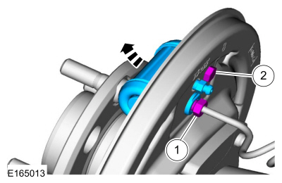
Disconnect the brake tube fitting.
Torque: 159 lb.in (18 Nm) Remove the bolt and wheel cylinder.
Torque: 106 lb.in (12 Nm)
 Disconnect the brake shoe lever fitting and re
Copyright © 2025 www.fofiesta7.com
