Ford Fiesta: Drum Brake / Brake Backing Plate. Removal and Installation
Ford Fiesta 2014 - 2019 Service Manual / Brake System / Drum Brake / Brake Backing Plate. Removal and Installation
Removal
NOTE: Removal steps in this procedure may contain installation details.
-
Remove the brake shoes.
Refer to: Brake Shoes (206-02 Drum Brake, Removal and Installation).
-
-
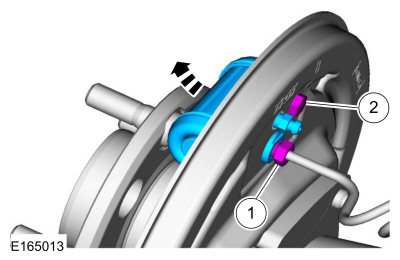
Disconnect the brake tube fitting.
Torque: 159 lb.in (18 Nm)
-
Remove the bolt and wheel cylinder.
Torque: 106 lb.in (12 Nm)
-
Disconnect the brake tube fitting.
 |
-
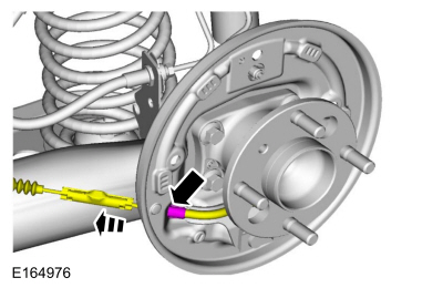
Disconnect the brake shoe lever fitting and remove the brake shoe lever.
 |
-
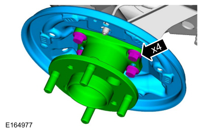
Remove the bolts, the wheel hub and bearing and the brake backing plate.
 |
Installation
-
To install, reverse the removal procedure.
-
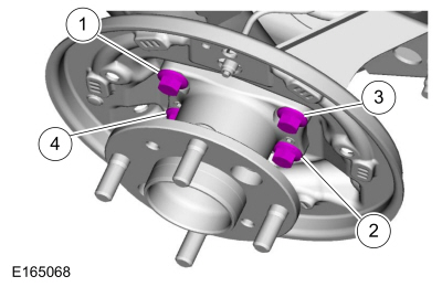
Install the brake backing plate, the wheel hub and bearing and the bolts.
Torque: 48 lb.ft (65 Nm)
|
-
-
Tighten the bolt in two stages.
Torque:
Stage 1: Loosen: 90°
Stage 2: 48 lb.ft (65 Nm)
-
Tighten the bolt in two stages.
Torque:
Stage 1: Loosen: 90°
Stage 2: 48 lb.ft (65 Nm)
-
Tighten the bolt in two stages.
Torque:
Stage 1: Loosen: 90°
Stage 2: 48 lb.ft (65 Nm)
-
Tighten the bolt in two stages.
Torque:
Stage 1: Loosen: 90°
Stage 2: 48 lb.ft (65 Nm)
-
Tighten the bolt in two stages.
 |
-
Bleed the brake system.
Refer to: Brake System Pressure Bleeding (206-00 Brake System - General Information, General Procedures).
 Brake Drum. Removal and Installation
Removal
NOTE:
Removal steps in this procedure may contain installation details.
WARNING:
Before beginning any service procedure in this
manual, refer to health and safety warnings in section 100-00 General
Information...
 Brake Shoes. Removal and Installation
Special Tool(s) /
General Equipment
Flat Headed Screw Driver
Materials
Name
Specification
Motorcraft® Silicone Brake Caliper Grease and Dielectric CompoundXG-3-A
ESA-M1C200-AESE-M1C171-A
Removal
NOTE:
Removal steps in this procedure may contain installation details...
Other information:
Ford Fiesta 2014 - 2019 Service Manual: Corrosion Prevention. General Procedures
Special Tool(s) / General Equipment Rust Protection Coating Gun Undercoating Gun Materials Name Specification ValuGard™ Premium UndercoatingVG101, VG101A - ValuGard™ Rust InhibitorVG104, VG104A - Motorcraft® Metal Surface Prep WipesZC-31-B - Repair NOTE: Undercoating NOTE: The follo..
Ford Fiesta 2014 - 2019 Service Manual: Front Door Tweeter Speaker. Removal and Installation
Removal Remove the front door handle. Refer to: Interior Front Door Handle (501-14 Handles, Locks, Latches and Entry Systems, Removal and Installation). Release the tabs and remove the front door tweeter speaker. Disconnect the electrical connector. Installation To install, reverse the removal pr..
Categories
- Manuals Home
- Ford Fiesta Service Manual (2014 - 2019)
- Maintenance Schedules - Gasoline Engines. Description and Operation
- Engine - 1.6L EcoBoost (132kW/180PS) – Sigma
- General Information
- Engine System - General Information
- Manual Transmission - 6-Speed Manual Transmission – B6
Brake Drum. Removal and Installation
Removal
NOTE: Removal steps in this procedure may contain installation details.
 WARNING:
Before beginning any service procedure in this
manual, refer to health and safety warnings in section 100-00 General
Information. Failure to follow this instruction may result in serious
personal injury.
WARNING:
Before beginning any service procedure in this
manual, refer to health and safety warnings in section 100-00 General
Information. Failure to follow this instruction may result in serious
personal injury.
Remove the wheel and tire.
Refer to: Wheel and Tire (204-04A Wheels and Tires, Removal and Installation).
Copyright © 2025 www.fofiesta7.com