Ford Fiesta: Drum Brake / Brake Drum. Removal and Installation
Ford Fiesta 2014 - 2019 Service Manual / Brake System / Drum Brake / Brake Drum. Removal and Installation
Removal
NOTE: Removal steps in this procedure may contain installation details.
-
Refer to: Health and Safety Precautions (100-00 General Information, Description and Operation). WARNING:
Before beginning any service procedure in this
manual, refer to health and safety warnings in section 100-00 General
Information. Failure to follow this instruction may result in serious
personal injury.
WARNING:
Before beginning any service procedure in this
manual, refer to health and safety warnings in section 100-00 General
Information. Failure to follow this instruction may result in serious
personal injury.
-
Remove the wheel and tire.
Refer to: Wheel and Tire (204-04A Wheels and Tires, Removal and Installation).
-
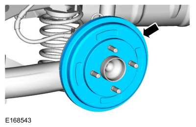
NOTICE: Use of a brake drum puller or a torch is not recommended. Brake drum distortion can result .
NOTE: If the brake drum is seized to the wheel hub pilot diameter, tap the center of the brake drum between the wheel studs.
Remove the brake drum.
 |
Installation
-
To install, reverse the removal procedure.
 Brake Shoe Adjustment. General Procedures
Adjustment
NOTE:
The brake shoes and parking brake cables must both be
adjusted to assure correct rear drum brake and parking brake system
operation...
 Brake Backing Plate. Removal and Installation
Removal
NOTE:
Removal steps in this procedure may contain installation details.
Remove the brake shoes.
Refer to: Brake Shoes (206-02 Drum Brake, Removal and Installation)...
Other information:
Ford Fiesta 2014 - 2019 Service Manual: Engine - Overview. Description and Operation
Engine Information NOTE: When repairing engines, all parts must be contamination free. If contamination/foreign material is present when repairing an engine, premature engine failure may occur. NOTE: Specifications show the expected minimum or maximum condition...
Ford Fiesta 2014 - 2019 Service Manual: Seatbelt Shoulder Height Adjuster. Removal and Installation
Removal NOTE: Removal steps in this procedure may contain installation details. Remove the B-pillar trim panel. Refer to: B-Pillar Trim Panel (501-05 Interior Trim and Ornamentation, Removal and Installation). Remove the bolt...
Categories
- Manuals Home
- Ford Fiesta Service Manual (2014 - 2019)
- Valve Clearance Adjustment. General Procedures
- Front Subframe. Removal and Installation
- Engine Cooling - 1.6L EcoBoost (132kW/180PS) – Sigma
- Manual Transmission, Clutch, Transfer Case and Power Transfer Unit
- Engine System - General Information
Rear Wheel Speed Sensor. Removal and Installation
Removal
NOTE: Removal steps in this procedure may contain installation details.
Remove the retainer and pull the rear splash shield outward. Disconnect the electrical connector and detach the wiring retainer.
Copyright © 2025 www.fofiesta7.com