Ford Fiesta: Engine - 1.6L EcoBoost (132kW/180PS) – Sigma / Valve Clearance Adjustment. General Procedures
Special Tool(s) / General Equipment
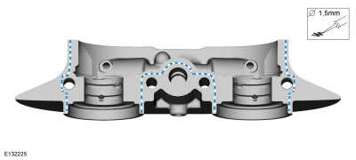
| Feeler Gauge |
Materials
| Name | Specification |
|---|---|
| Engine Oil - SAE 5W-20 - Synthetic Blend Motor Oil XO-5W20-Q1SP |
WSS-M2C945-B1 |
| Flange Sealant CU7Z-19B508-A |
WSS-M2G348-A11 |
Check
-
Refer to: Valve Cover (303-01B Engine - 1.6L EcoBoost (132kW/180PS) – Sigma, Removal and Installation).
-
NOTICE: Only use hand tools when removing or installing the spark plugs, or damage can occur to the cylinder head or spark plug.
NOTE:
Use compressed air to remove any foreign material in the spark plug well before removing the spark plugs.
 |
 |
-
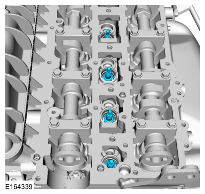
NOTE: Turn the engine clockwise only and use the crankshaft bolt only.
NOTE: Measure the valve clearance at base circle, with the lobe pointed away from the tappet, before removing the camshafts. Failure to measure all clearances prior to removing the camshafts will necessitate repeated removal and installation and wasted labor time.
Measure each valve's clearance and record its location.
Use the General Equipment: Feeler Gauge
 |
-
NOTE: The nominal clearance is:
- intake: 0.0118 in (0.3 mm)
- exhaust: 0.0157 in (0.4 mm)
NOTE: The acceptable clearance is:
- intake: 0.010–0.014 in (0.255–0.345 mm)
- exhaust: 0.014–0.018 in (0.355–0.445 mm)
Adjustment
-
Refer to: Camshafts (303-01B Engine - 1.6L EcoBoost (132kW/180PS) – Sigma, Removal and Installation).
-
NOTE: The number on the valve tappet only reflects the digits that follow the decimal. For example, a tappet with the number has the thickness of 3.650 mm.
NOTE: Select the closest tappet size to the ideal tappet thickness available and mark the installation location.
Select tappets using this formula: tappet thickness = measured clearance + the existing tappet thickness - nominal clearance.
-
Install the correct valve tappet.
-
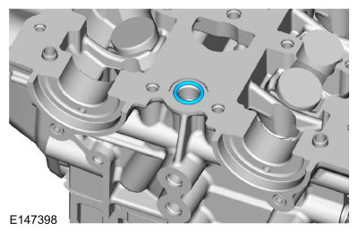
NOTE: Install a new O-ring seal.
 |
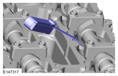
- Material: Flange Sealant / CU7Z-19B508-A (WSS-M2G348-A11)
 |
-
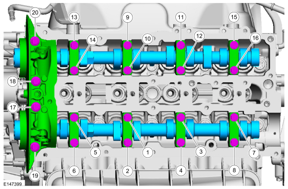
NOTICE: Failure to follow the camshaft tightening procedure can result in damage to the camshafts.
NOTE: Make sure that the components are installed to the location and orientation noted before removal.
NOTE: Make sure that the mating faces are clean and free of foreign material.
NOTE: Make sure that new bolts are installed.
NOTE: Apply clean engine oil to the bearing surfaces of the camshafts, camshaft bearing caps and the VCT bridge.
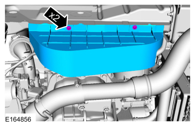
Tighten the bolts evenly, half turn at a time, until the crankshaft bearing caps and the VCT bridge are seated against the cylinder head.
Material: Engine Oil - SAE 5W-20 - Synthetic Blend Motor Oil / XO-5W20-Q1SP (WSS-M2C945-B1)
Torque:
Stage 1: 1 - 16: 62 lb.in (7 Nm)
Stage 2: 17 - 20: 89 lb.in (10 Nm)
Stage 3: 1 - 16: 45°
Stage 4: 17 and 18: 70°
Stage 5: 19 and 20: 53°
 |
-
-
Turn the crankshaft back by 45° (counterclock wise).
-
Turn the camshafts to measure the valve clearance,
-
Repeat the procedure as necessary until all the valve clearances are within specifications.
-
Turn the crankshaft clockwise until it stops against the special tool.
-
Turn the crankshaft back by 45° (counterclock wise).
-
NOTICE: Only use hand tools when removing or installing the spark plugs, or damage can occur to the cylinder head or spark plug.
NOTE:
Torque: 133 lb.in (15 Nm)
|
-
Refer to: Camshaft Seal (303-01B Engine - 1.6L EcoBoost (132kW/180PS) – Sigma, Removal and Installation).
|

 Camshaft Seal. Removal and Installation
Special Tool(s) /
General Equipment
303-1532Installer, Camshaft SealTKIT-2010B-FLMTKIT-2010B-ROW
303-409
(T92C-6700-CH)
Remover, Crankshaft SealTKIT-1992-FH/FMH/FLMHTKIT-1993-LMH/MH
Materials
Name
Specification
Engine Oil - SAE 5W-20 - Synthetic Blend Motor OilXO-5W20-Q1SP
WSS-M2C945-B1
Removal
Remove the VCT unit..
Other information:
Ford Fiesta 2014 - 2019 Service Manual: Rocker Panel - 5-Door. Removal and Installation
Special Tool(s) / General Equipment Resistance Spotwelding Equipment Hot Air Gun Air Body Saw MIG/MAG Welding Equipment Spot Weld Drill Bit Locking Pliers Folding Rule Materials Name Specification Metal Bonding AdhesiveTA-1, TA-1-B, 3M™ 08115, LORD Fusor® 108B, Henkel Teroson EP 5055 - Removal ..
Ford Fiesta 2014 - 2019 Service Manual: Gearshift Lever. Removal and Installation
Removal Remove the floor console. Refer to: Floor Console (501-12 Instrument Panel and Console, Removal and Installation). Disconnect the gearshift cable ends from the ball studs, slide the lock sleeve and remove the gearshift cables from the gearshift lever. Remove the nuts and the gearshift lever. Torque..
Categories
- Manuals Home
- Ford Fiesta Service Manual (2014 - 2019)
- Maintenance Schedules - Gasoline Engines. Description and Operation
- Engine Component View. Description and Operation
- Front Subframe. Removal and Installation
- Manual Transmission - 6-Speed Manual Transmission – B6
- Engine
Brake Master Cylinder. Removal and Installation
Removal
NOTICE: If the fluid is spilled on the paintwork, the affected area must be immediately washed down with cold water.
NOTE: Removal steps in this procedure may contain installation details.
All vehicles
Remove the battery tray.Refer to: Battery Tray - 1.6L Duratec-16V Ti-VCT (88kW/120PS) – Sigma (414-01 Battery, Mounting and Cables, Removal and Installation).
Refer to: Battery Tray - 1.6L EcoBoost (132kW/180PS) – Sigma (414-01 Battery, Mounting and Cables, Removal and Installation).
Disconnect the vacuum tube from the brake booster and detach the routing clip.