Ford Fiesta: Manual Transmission External Controls - 5-Speed Manual Transmission – B5/IB5/6-Speed Manual Transmission – B6 / Gearshift Lever. Removal and Installation
Removal
-
Remove the floor console.
Refer to: Floor Console (501-12 Instrument Panel and Console, Removal and Installation).
-
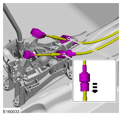
Disconnect the gearshift cable ends from the ball studs,
slide the lock sleeve and remove the gearshift cables from the
gearshift lever.
 |
-
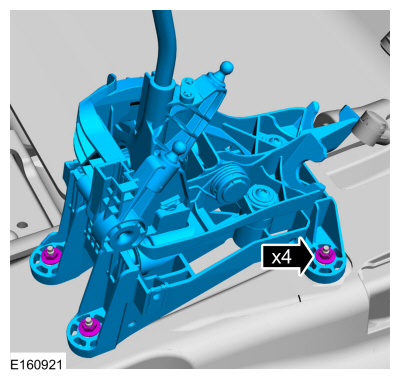
Remove the nuts and the gearshift lever.
Torque: 80 lb.in (9 Nm)
 |
Installation
-
To install, reverse the removal procedure.
-
Adjust the selector lever cable.
Refer to: Gearshift Cable Adjustment - 6-Speed Manual Transmission – B6 (308-06 Manual Transmission External Controls - 5-Speed Manual Transmission – B5/IB5/6-Speed Manual Transmission – B6, General Procedures).
Refer to: Gearshift Cable Adjustment - 5-Speed Manual Transmission – B5/IB5 (308-06 Manual Transmission External Controls - 5-Speed Manual Transmission – B5/IB5/6-Speed Manual Transmission – B6, General Procedures).
 Gearshift Lever Boot. Removal and Installation
Special Tool(s) /
General Equipment
Interior Trim Remover
Removal
NOTE:
Removal steps in this procedure may contain installation details...
 Gearshift Cables - 6-Speed Manual Transmission – B6. Removal and Installation
Removal
With the vehicle in N , position it on a hoist.
Refer to: Jacking and Lifting - Overview (100-02 Jacking and Lifting, Description and Operation)...
Other information:
Ford Fiesta 2014 - 2019 Service Manual: Reset the SYNC Module [APIM]. General Procedures
Programming NOTE: An APIM Reset consists of a battery disconnect and a SYNC® system Master Reset. It may not be necessary to perform a Master Reset after disconnecting the battery if the concern is resolved. NOTE: This procedure clears all Continuous Memory Diagnostic Trouble Codes (CMDTCs)...
Ford Fiesta 2014 - 2019 Service Manual: Passive Anti-Theft System (PATS) Front Antenna. Removal and Installation
Removal Remove the selector lever assembly and gearshift lever. Refer to: Selector Lever Assembly (307-05 Automatic Transmission External Controls - 6-Speed PowerShift Transmission – DPS6/6DCT250, Removal and Installation). Refer to: Gearshift Lever (308-06 Manual Transmission External Controls - 5-Speed Manual Transmission – B5/IB5/6-Speed Manual Transmission – B6, Re..
Categories
- Manuals Home
- Ford Fiesta Service Manual (2014 - 2019)
- Manual Transmission, Clutch, Transfer Case and Power Transfer Unit
- Front Suspension
- Service Information
- Engine
- Manual Transmission - 6-Speed Manual Transmission – B6
Component Bleeding. General Procedures
Special Tool(s) / General Equipment
Master Cylinder Bleeding SetBleeding
NOTICE: If the fluid is spilled on the paintwork, the affected area must be immediately washed down with cold water.
Master Cylinder
NOTE: When a new brake master cylinder has been installed, it should be primed to prevent air from entering the system.
NOTE: Make sure the area around the master cylinder cap is clean and free of foreign material.
Remove the brake fluid reservoir cap.Copyright © 2025 www.fofiesta7.com
