Ford Fiesta: Brake System - General Information / Component Bleeding. General Procedures
Ford Fiesta 2014 - 2019 Service Manual / Brake System / Brake System - General Information / Component Bleeding. General Procedures
Special Tool(s) / General Equipment
| Master Cylinder Bleeding Set |
Bleeding
NOTICE: If the fluid is spilled on the paintwork, the affected area must be immediately washed down with cold water.
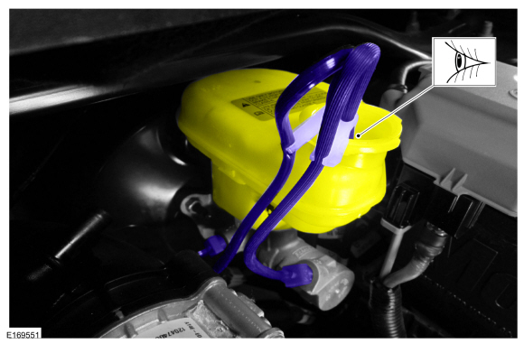
Master Cylinder
NOTE: When a new brake master cylinder has been installed, it should be primed to prevent air from entering the system.
-
NOTE: Make sure the area around the master cylinder cap is clean and free of foreign material.
Remove the brake fluid reservoir cap.
 |
-
Fill the reservoir with clean, specified brake fluid.
 |
-
Loosen and remove the brake tube fittings.
 |
-
Install the master cylinder bleeding set.
Use the General Equipment: Master Cylinder Bleeding Set
 |
-
Have an assistant pump the brake pedal slowly until clear bubble free fluid flows from the brake tubes.
 |
-
Remove the master cylinder bleeding set.
Remove the General Equipment: Master Cylinder Bleeding Set
 |
-
Tighten the brake tube fittings.
 |
-
Fill the reservoir with clean, specified brake fluid.
 |
-
Refer to: Brake System Pressure Bleeding - Vehicles With: Vacuum Brake Booster (206-00)
.
Brake Caliper, Wheel Cylinder, Brake Hose or Brake Tube
-
NOTE: Pressure bleeding the brake system is required anytime a hydraulic brake system component has been disconnected.
Refer to: Brake System Pressure Bleeding - Vehicles With: Vacuum Brake Booster (206-00) .
 Brake System. Diagnosis and Testing
Symptom Chart(s)
Symptom Chart: Brake System
Diagnostics in this manual assume a certain skill level and knowledge of Ford-specific diagnostic practices...
 Brake Disc Machining. General Procedures
Repair
WARNING:
Service actions on vehicles equipped with electronic parking
brakes may cause unexpected parking brake application, which could
result in injury to hands or fingers...
Other information:
Ford Fiesta 2014 - 2019 Service Manual: Parking Aid - System Operation and Component Description. Description and Operation
System Operation System Diagram Item Description 1 Video camera 2 IPC 3 TCM 4 LIN 5 Video signal 6 Infotainment Controller Area Network (I-CAN) 7 HS-CAN 8 MS-CAN 9 PCM 10 Reversing lamp switch 11 Manual transm..
Ford Fiesta 2014 - 2019 Service Manual: Fuel Charging and Controls. Diagnosis and Testing
General Equipment Ford diagnostic equipment Diagnostics in this manual assume a certain skill level and knowledge of Ford-specific diagnostic practices. For information about these, REFER to: Diagnostic Methods (100-00 General Information, Description and Operation). For PCM DTC , REFER to: Electronic Engine Controls (303-14B Electronic Engine Controls - 1.6L Ec..
Categories
- Manuals Home
- Ford Fiesta Service Manual (2014 - 2019)
- Manual Transmission - 6-Speed Manual Transmission – B6
- Service Information
- Body Control Module (BCM). Removal and Installation
- Engine System - General Information
- Maintenance Schedules - Gasoline Engines. Description and Operation
Wheels and Tires. Diagnosis and Testing
Preliminary Inspection
Verify the customer concern by carrying out a road test on a smooth road. If any vibrations are apparent, Refer to the Symptom Chart: NVH.To maximize tire performance, inspect for signs of incorrect inflation and uneven wear, which may indicate a need for balancing, rotation or front suspension alignment.
Correct tire pressure and driving techniques have an important influence on tire life. Heavy cornering, excessively rapid acceleration and unnecessary sharp braking increase tire wear.
Correct tire pressure and driving techniques have an important influence on tire life. Heavy cornering, exce
Copyright © 2025 www.fofiesta7.com
