Ford Fiesta: Engine - 1.6L EcoBoost (132kW/180PS) – Sigma / Engine. Description and Operation
Overview
The 1.6L GTDI 4-cylinder engine has the following features:
- Dual overhead camshafts
- Four valves per cylinder
- Composite intake manifold
- Aluminum cylinder head
- Aluminum cylinder block
- Gasoline turbocharged direct injection (GTDI)
- Twin independent variable cam timing (Ti-VCT)
Engine Identification
Always refer to these labels when installation of new parts is necessary or when checking engine calibrations. The engine parts often differ within a CID family. Verification of the identification codes will make sure the correct parts are obtained. These codes contain all the pertinent information relating to the dates, optional equipment and revisions.
Engine Code Information Label
The engine code information label, located on the front side of the timing cover, contains the following:
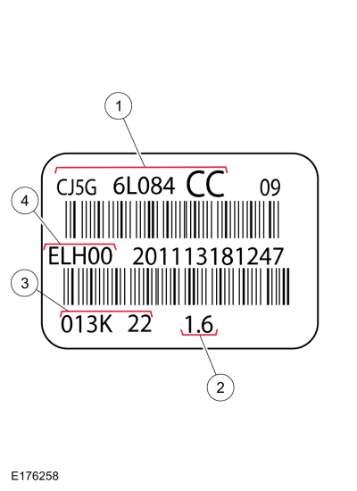
| Item | Description |
|---|---|
| 1 | Engine part number |
| 2 | Engine displacement - 1.6L |
| 3 | Engine build date - 0YYM(A-L)DD |
| 4 | Plant code - Bridgend |
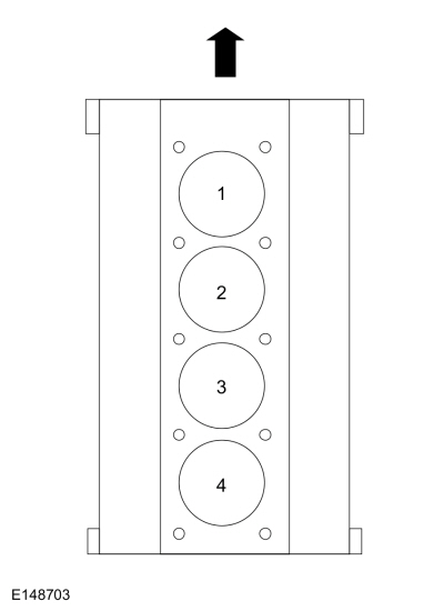
Engine Cylinder Identification
System Operation
Lubrication System
The engine lubrication system is of the force-feed type in which oil is supplied under full pressure to the crankshaft, connecting rod bearings, camshaft bearing caps and variable camshaft timing (VCT) solenoids. The flow of oil to the valve tappets and valve train is controlled by a restricting orifice located in the cylinder head gasket.
The lubrication system is designed to provide optimum oil flow to critical components of the engine through its entire operating range.
The heart of the system is a positive displacement internal gear oil pump.
Generically, this design is known as a variable oil pump or vane-type pump, which operates as follows:
- The oil pump is driven from the crankshaft.
- System pressure is limited by an integral, internally-vented relief valve which directs the bypassed oil back to the inlet side of the oil pump.
- Oil pump displacement has been selected to provide adequate volume to make sure of correct oil pressure both at hot idle and maximum speed.
- The relief valve calibration protects the system from excessive pressure during high-viscosity conditions.
- The relief valve is designed to provide adequate connecting rod bearing lubrication under high temperature and high-speed conditions.
Valve Train
The valve train uses direct acting mechanical buckets (DAMB). The camshaft lobes are positioned directly above mechanical buckets which are positioned on top of the valves.
Twin Independent Variable Cam Timing (Ti-VCT)
The Ti-VCT system allows variable control of the valves which optimizes combustion at full load providing improved power and low speed torque (broadening the torque curve) which enables variable valve overlap which provides better fuel economy and emissions and provides optimized cold start operation with improved exhaust emissions.

 Valve Clearance Adjustment. General Procedures
Special Tool(s) /
General Equipment
Feeler Gauge
Materials
Name
Specification
Engine Oil - SAE 5W-20 - Synthetic Blend Motor OilXO-5W20-Q1SP
WSS-M2C945-B1
Flange SealantCU7Z-19B508-A
WSS-M2G348-A11
Check
Refer to: Valve Cover (303-01B Engine - 1...
Other information:
Ford Fiesta 2014 - 2019 Service Manual: Interior Rear Door Handle. Removal and Installation
Removal NOTE: LH side shown, RH side similar. Remove the rear door trim panel. Refer to: Rear Door Trim Panel (501-05 Interior Trim and Ornamentation, Removal and Installation). Release the retaining clips and remove the interior rear door handle...
Ford Fiesta 2014 - 2019 Service Manual: Passenger Side Register. Removal and Installation
Special Tool(s) / General Equipment Interior Trim Remover Removal NOTE: Removal steps in this procedure may contain installation details. Remove the passenger side register assembly. Use the General Equipment: Interior Trim Remover Installation To install, reverse the removal procedure...
Categories
- Manuals Home
- Ford Fiesta Service Manual (2014 - 2019)
- Fuel Rail. Removal and Installation
- Engine - 1.6L EcoBoost (132kW/180PS) – Sigma
- Front Suspension
- Engine Cooling - 1.6L EcoBoost (132kW/180PS) – Sigma
- Camshafts. Removal and Installation
Parking Brake Control. Removal and Installation
Removal
NOTE: Removal steps in this procedure may contain installation details.
Remove the floor console.Refer to: Floor Console (501-12 Instrument Panel and Console, Removal and Installation).
Remove the driver seat.
Refer to: Front Seat (501-10 Seating, Removal and Installation).
Remove the parking brake cable adjustment lock nut.
 Loosen the parking brake cable adjustment nut.