Ford Fiesta: Power Brake Actuation / Brake Booster. Removal and Installation
Removal
NOTE: Removal steps in this procedure may contain installation details.
-
Remove the brake master cylinder.
Refer to: Brake Master Cylinder (206-06 Hydraulic Brake Actuation, Removal and Installation).
-
NOTICE: Do not service the brake pedal or brake booster without first removing the stoplamp switch. This switch must be removed with the brake pedal in the at-rest position. The switch plunger must be compressed for the switch to rotate in the bracket. Attempting to remove the switch when the plunger is extended (during pedal apply) will result in damage to the switch.
Remove the stoplamp switch.
Refer to: Stoplamp Switch (417-01 Exterior Lighting, Removal and Installation).
-
NOTICE: Do not service the brake pedal or brake booster without first removing the cruise control deactivator switch. This switch must be removed with the brake pedal in the at-rest position. The switch plunger must be compressed for the switch to rotate in the bracket. Attempting to remove the switch when the plunger is extended (during pedal apply) will result in damage to the switch.
Remove the cruise control deactivator switch.
Refer to: Cruise Control Deactivator Switch (419-03 Cruise Control, Removal and Installation).
-
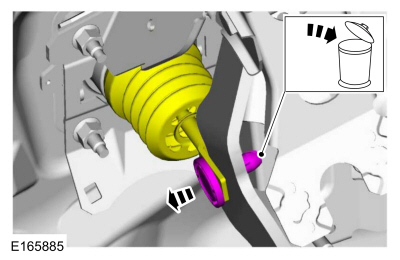
NOTE: The booster push rod clevis-locking pin is a one-time use only part. Any time the booster push rod clevis-locking pin is removed, a new booster push rod clevis-locking pin should be used.
Compress the tabs and remove the clevis pin. Discard the pin.
 |
-
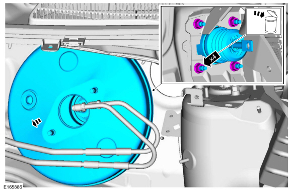
Remove the nuts and brake booster. Discard the nuts.
Torque: 18 lb.ft (25 Nm)
 |
Installation
-
NOTICE: Do not press, pull or otherwise move the brake pedal while installing the stoplamp switch and cruise control deactivator switch. Install these switches with the booster push rod attached to the brake pedal and with the brake pedal in the at-rest position. Installing these switches with the brake pedal in any other position will result in incorrect adjustment and may damage the switches.
To install, reverse the removal procedure.
 Brake Vacuum Pump - 1.6L EcoBoost (132kW/180PS) – Sigma. Removal and Installation
Materials
Name
Specification
Flange Sealant - AnaerobicLoctite® 51031
WSK-M2G348-A7
Removal
NOTE:
Removal steps in this procedure may contain installation details...

Other information:
Ford Fiesta 2014 - 2019 Service Manual: Radiator Lower Hose. Removal and Installation
Special Tool(s) / General Equipment Hose Clamp Remover/Installer Removal Drain the cooling system. Refer to: Engine Cooling System Draining, Vacuum Filling and Bleeding (303-03B Engine Cooling - 1.6L EcoBoost (132kW/180PS) – Sigma, General Procedures). Remove the generator. Refer to: Generator - 1.6L EcoBoost (132kW/180PS) – Sigma (414-0..
Ford Fiesta 2014 - 2019 Service Manual: SYNC Module [APIM] to Universal Serial Bus (USB) Port Cable. Removal and Installation
Special Tool(s) / General Equipment Interior Trim Remover Removal All vehicles Release the retainers and remove the bracket. Open the glove compartment door and remove the glove compartment. Vehicles with manual transmission Remove the manual transmission shifte..
Categories
- Manuals Home
- Ford Fiesta Service Manual (2014 - 2019)
- Front Subframe. Removal and Installation
- Front Suspension
- Maintenance Schedules
- Clutch - 6-Speed Manual Transmission – B6
- Climate Control System - General Information
Front Strut and Spring Assembly. Removal and Installation
Removal
NOTE: Removal steps in this procedure may contain installation details.
NOTE: This step is only necessary when installing a new component to the left-hand side.
Remove the nuts and position aside the remote brake fluid reservoir.Torque: 62 lb.in (7 Nm)
 Remove the strut and spring assembly upper mount nuts.
 Torque: 22 lb.ft (30 Nm)
