Ford Fiesta: Engine - 1.6L EcoBoost (132kW/180PS) – Sigma / Engine. Assembly
Special Tool(s) /
General Equipment
 |
100-002
(TOOL-4201-C)
Holding Fixture with Dial Indicator Gauge |
 |
300-OTC1819E
2,200# Floor Crane, Fold Away |
 |
303-103
(T74P-6375-A)
Holding Tool, Flywheel
T74P-77000-A
TKIT-2009TC-F |
 |
303-1097
Locking Tool, Variable Camshaft Timing Oil Control Unit
TKIT-2010B-FLM
TKIT-2010B-ROW |
 |
303-1502
Lifting Device Engine
TKIT-2012A-FL
TKIT-2012A-ROW |
 |
303-1532
Installer, Camshaft Seal
TKIT-2010B-FLM
TKIT-2010B-ROW |
 |
303-1550
Alignment Tool, Crankshaft Vibration Damper
TKIT-2012A-FL
TKIT-2012A-ROW |
 |
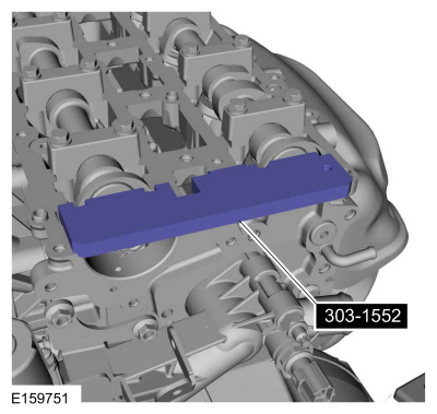
303-1552
Alignment Tool, Camshaft
TKIT-2012A-FL
TKIT-2012A-ROW |
 |
303-1567
Sizer, Teflon Seal
TKIT-2010C-FLM |
 |
303-175
(T82L-6316-A)
Installer, Crankshaft Vibration Damper
TKIT-1982-F |
 |
303-335
(T88T-6701-A)
Installer, Front Cover Oil Seal
TKIT-1988-FLM
TKIT-1988-F |
 |
303-393-02
Adapter for 303-393
TKIT-2012A-FL
TKIT-2012A-ROW |
 |
303-393A
Locking Tool, Flywheel
TKIT-2012A-FL
TKIT-2012A-ROW |
 |
303-420
(T92P-6701-BH)
Installer, Crankshaft Front Oil Seal
TKIT-1992-FLMH/LMH
TKIT-1992-LMH/MH |
 |
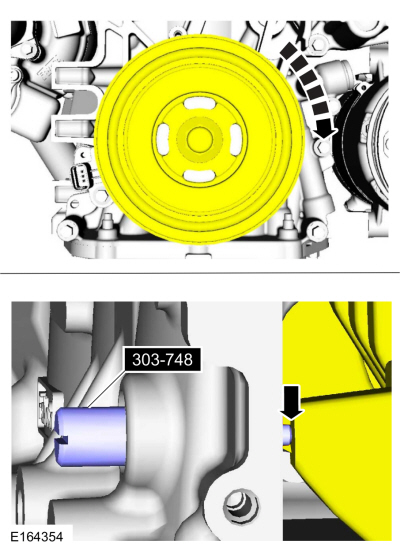
303-748
Locking Tool, Crankshaft
TKIT-2010B-FLM
TKIT-2010B-ROW |
 |
310-205
Fuel Injector Brush |
 |
310-207
Installer, Fuel Injector Seal Assembly
TKIT-2009A-FLM |
| Feeler Gauge |
| Hose Clamp Remover/Installer |
| Piston Ring Compressor |
Materials
| Name |
Specification |
Motorcraft® Thread Sealant with PTFE
TA-24-B |
WSK-M2G350-A2
|
Motorcraft® High Performance Engine RTV Silicone
TA-357 |
WSE-M4G323-A6
|
Flange Sealant
CU7Z-19B508-A |
WSS-M2G348-A11
|
Motorcraft® Metal Surface Prep Wipes
ZC-31-B |
-
|
Engine Oil - SAE 5W-20 - Synthetic Blend Motor Oil
XO-5W20-Q1SP |
WSS-M2C945-B1
|
Flange Sealant - Anaerobic
Loctite® 51031 |
WSK-M2G348-A7
|
Motorcraft® Silicone Brake Caliper Grease and Dielectric Compound
XG-3-A |
ESA-M1C200-A
ESE-M1C171-A
|
NOTICE:
During engine repair procedures, cleanliness is extremely
important. Any foreign material, including any material created while
cleaning gasket surfaces that enters the oil passages, coolant passages
or the oil pan, can cause engine failure.
NOTE:
Refer to exploded views in Description and Operation.
-
Torque:
80 lb.in (9 Nm)
-
-
Measure the length in two directions.
-
Record the smallest measurement for each crankshaft main bearing journal.
-
Mounted flush and finger tight.
-
Torque:
Stage 1:
22 lb.ft (30 Nm)
Stage 2:
37 lb.ft (50 Nm)
Stage 3:
45°
Stage 4:
Tighten an additional::
45°
-
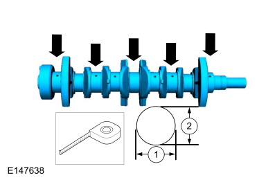
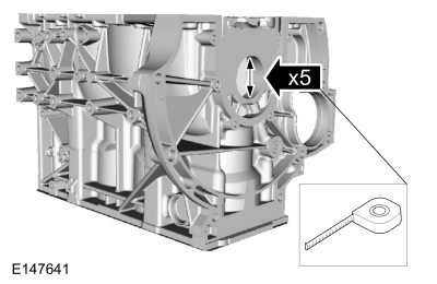
Measure the length in five places.
-
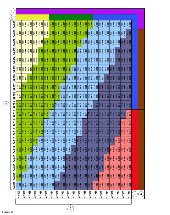
Using the chart, select the correct grade main bearings.
-
Cylinder block bore diameter
-
Crankshaft journal diameter
-
Upper bearing color code
-
Lower bearing color code
-
NOTICE:
The rod cap installation must keep the same orientation as marked during disassembly or engine damage may occur.
Use the original connecting rod cap bolts.
Torque:
Stage 1:
159 lb.in (18 Nm)
Stage 2:
45°
Stage 3:
Tighten an additional::
45°
-
-
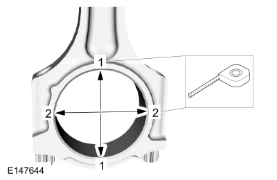
Measure the length or distance in two directions.
-
Record the smallest measurement for each connecting rod.
-
-
-
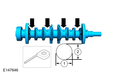
Measure the length in two directions.
-
Record the smallest measurement for each connecting rod journal.
-
Using the chart, select the correct grade connecting rod bearings for each crankshaft connecting rod journal.
-
Connecting rod bore diameter
-
Crankshaft connecting rod journal diameter
-
Upper bearing color code
-
Lower bearing color code
-
-
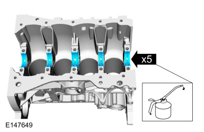
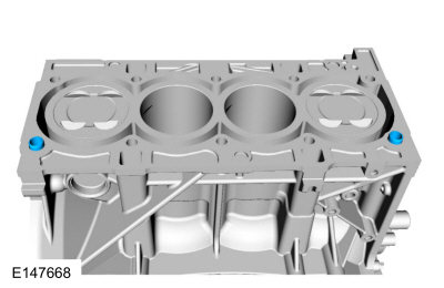
NOTE:
Before assembling the cylinder block, all sealing
surfaces must be free of chips, dirt, paint and foreign material. Also,
make sure the coolant and oil passages are clear.
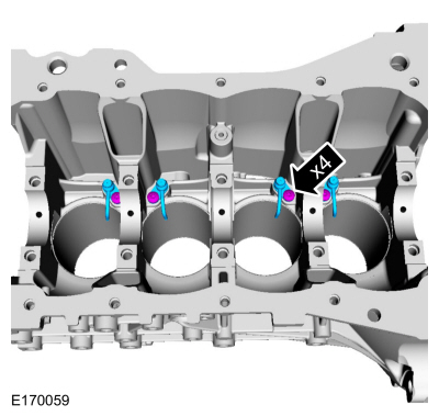
NOTE:
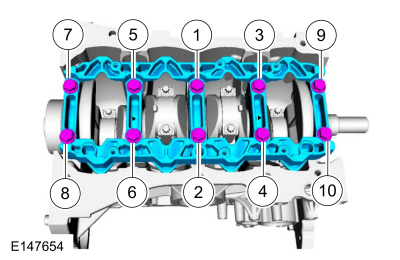
If reusing the crankshaft main bearings, install them in
their original positions and orientation as noted during disassembly.
Material: Engine Oil - SAE 5W-20 - Synthetic Blend Motor Oil
/ XO-5W20-Q1SP
(WSS-M2C945-B1)
-
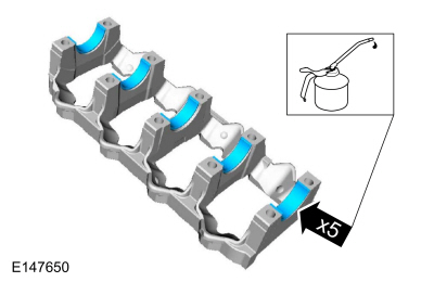
NOTE:
If reusing the crankshaft main bearings, install them in
their original positions and orientation as noted during disassembly.
Material: Engine Oil - SAE 5W-20 - Synthetic Blend Motor Oil
/ XO-5W20-Q1SP
(WSS-M2C945-B1)
-
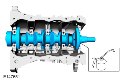
Material: Engine Oil - SAE 5W-20 - Synthetic Blend Motor Oil
/ XO-5W20-Q1SP
(WSS-M2C945-B1)
-
Material: Engine Oil - SAE 5W-20 - Synthetic Blend Motor Oil
/ XO-5W20-Q1SP
(WSS-M2C945-B1)
-
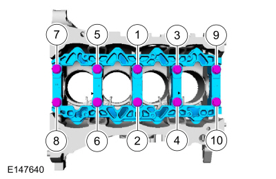
Mounted flush.
-
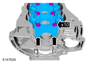
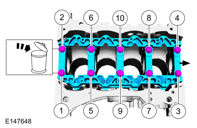
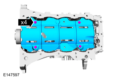
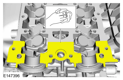
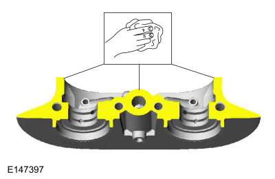
NOTE:
Lubricate the main bearing beam bolts threads with clean engine oil.
Material: Engine Oil - SAE 5W-20 - Synthetic Blend Motor Oil
/ XO-5W20-Q1SP
(WSS-M2C945-B1)
Torque:
Stage 1:
22 lb.ft (30 Nm)
Stage 2:
37 lb.ft (50 Nm)
Stage 3:
45°
Stage 4:
Tighten an additional::
45°
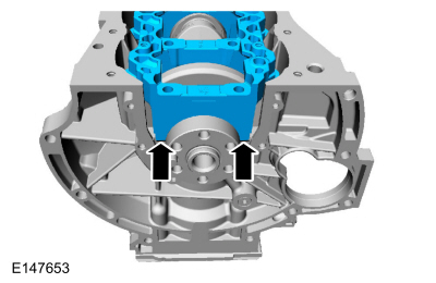
-
-
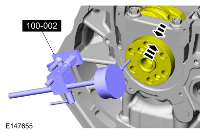
Position the crankshaft to the rear of the cylinder block.
-
Zero the Dial Indicator Gauge with Holding Fixture.
Use Special Service Tool: 100-002
(TOOL-4201-C)
Holding Fixture with Dial Indicator Gauge.
-
Move the crankshaft to the front of the cylinder block. Note and record the crankshaft end play.
-
Acceptable crankshaft end play is 0.12-0.43 mm
(0.008-0.017 in). If the crankshaft end play exceeds the specified
range, install new parts as necessary.
-
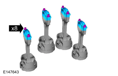
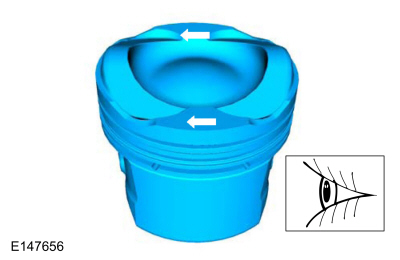
Arrows faces the front of the engine.
-
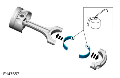
NOTE:
If reusing the connecting rod bearings, install them in
their original positions and orientation as noted during disassembly.
Material: Engine Oil - SAE 5W-20 - Synthetic Blend Motor Oil
/ XO-5W20-Q1SP
(WSS-M2C945-B1)
-
-
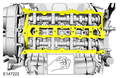
NOTE:
The upper and lower compression rings are to be fitted with the identification marks on the upper side.
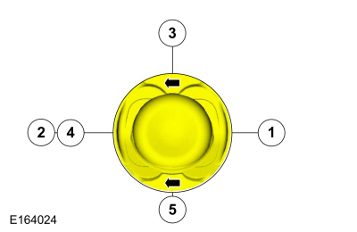
NOTE:
Arrows faces the front of the engine.
NOTE:
Align the piston rings on the piston.
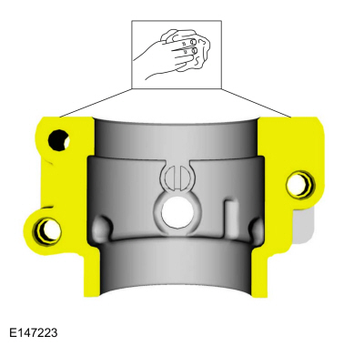
-
Upper compression ring gap location.
-
Lower compression ring gap location.
-
Upper oil control segment ring gap location.
-
Expander ring gap location.
-
Lower oil control segment ring gap location.
-
NOTE:
Using a connecting rod installer will unsure not to
scratch the cylinder wall or crankshaft journal with the connecting rod.
Push the piston down until the connecting rod bearing seats on the
crankshaft journal.
NOTE:
Make sure the piston arrows on top is facing toward the front of the engine.
Use the General Equipment: Piston Ring Compressor
Material: Engine Oil - SAE 5W-20 - Synthetic Blend Motor Oil
/ XO-5W20-Q1SP
(WSS-M2C945-B1)
 |
|
-
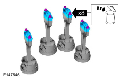
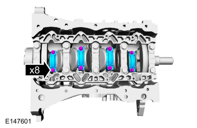
NOTICE:
The rod cap installation must keep the same orientation as marked during disassembly or engine damage may occur.
NOTE:
Install connecting rod caps and bolts on the connecting
rods for cylinders 1 and 4 first and tighten. Then rotate crankshaft 180
degrees and install connecting rod caps and bolts on connecting rods
for cylinders 2 and 3 and tighten.
NOTE:
After installation of each connecting rod cap, rotate the crankshaft to verify smooth operation.
Use new connecting rod caps bolts.
Torque:
Stage 1:
159 lb.in (18 Nm)
Stage 2:
45°
Stage 3:
Tighten an additional::
45°
-
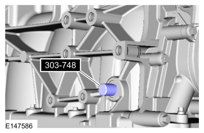
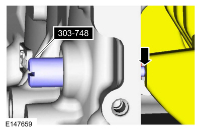
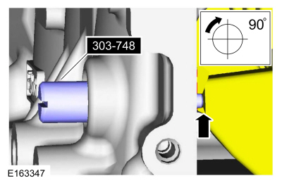
Install Special Service Tool: 303-748
Locking Tool, Crankshaft.
-
NOTE:
Only rotate the crankshaft clockwise direction.
Rotate the crankshaft slowly clockwise until the crankshaft
balance weight is up against the crankshaft locking tool. The engine is
now at TDC .
-
-
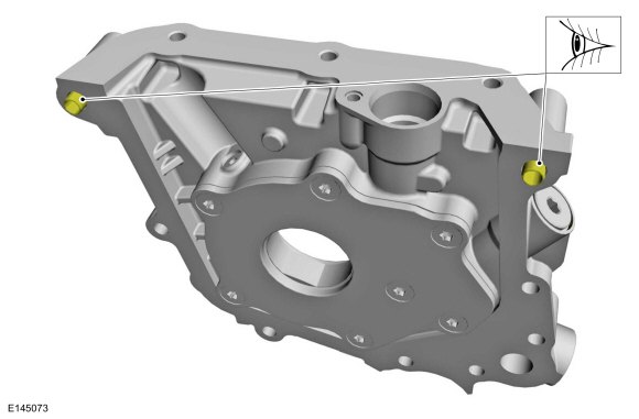
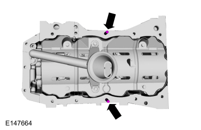
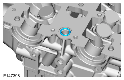
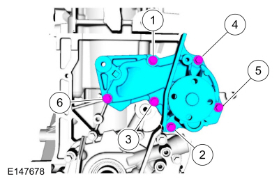
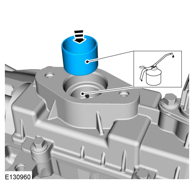
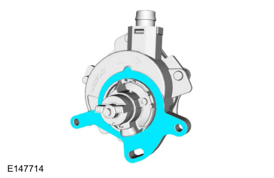
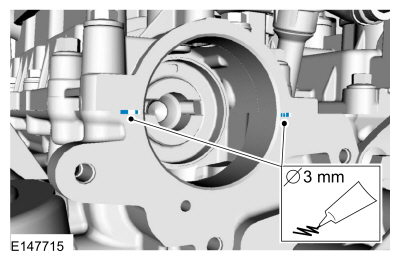
NOTE:
Make sure that the locating dowels remain installed.
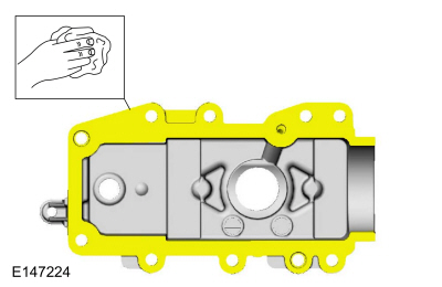
Inspect the oil pump locating dowels for damage and correct installation.
-
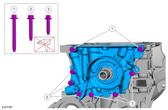
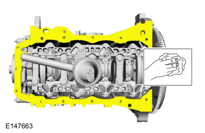
Prime the oil pump. Add 2 tablespoons of clean engine oil to the oil pump and rotate the oil pump by hand.
-
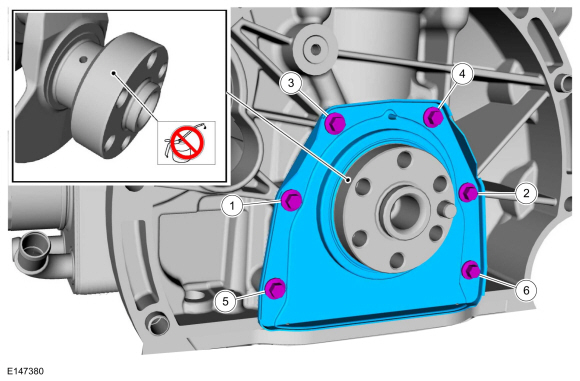
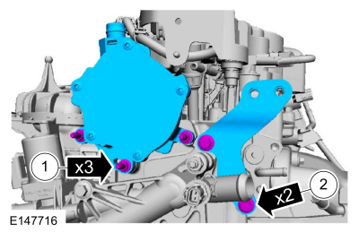
NOTE:
Only tighten the bolts finger tight at this stage.
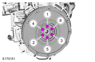
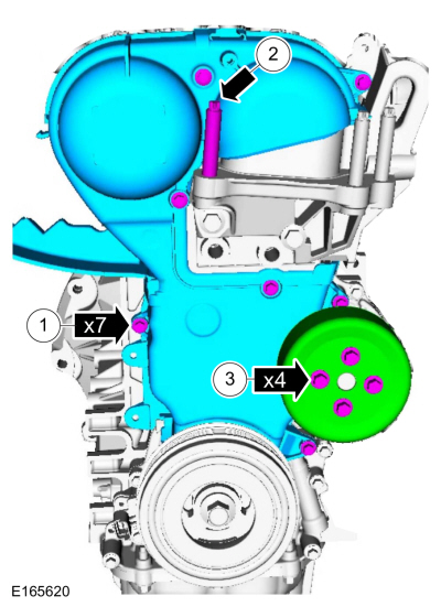
Install the oil pump and follow the steps below. Hand start the bolts.
-
Install the two M6 x 55 mm bolts finger tight.
-
Install the three M6 x 35 mm bolts finger tight.
-
Install the three M6 x 25 mm bolts finger tight.
-
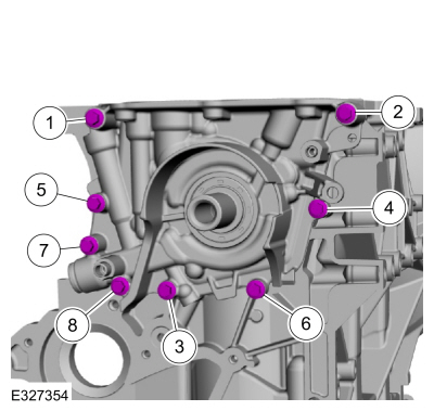
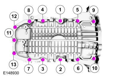
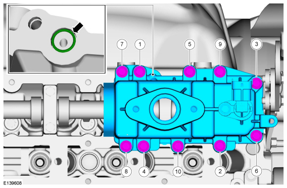
Tighten the oil pump bolts in sequence shown in 2 stages.
Torque:
Stage 1:
Tighten bolts 1, 2, 3 and 6:
18 lb.in (2 Nm)
Stage 2:
Tighten bolts 1 through 8:
97 lb.in (11 Nm)
-
Torque:
84 lb.in (9.5 Nm)
-
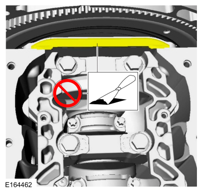
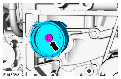
NOTE:
New crankshaft rear seal is supplied with an alignment sleeve which must be removed after installation.
NOTE:
Do not remove the alignment sleeve from the crankshaft rear seal prior to installation on the crankshaft.
Align the crankshaft rear seal and alignment sleeve on the
crankshaft and push the crankshaft rear seal off the alignment sleeve
onto the crankshaft without stopping until the crankshaft rear seal
meets the cylinder block.
Torque:
Stage 1:
35 lb.in (4 Nm)
Stage 2:
89 lb.in (10 Nm)
-
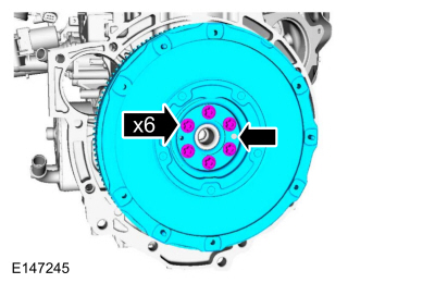
Finger tight.
-
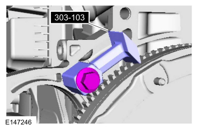
Install Special Service Tool: 303-103
(T74P-6375-A)
Holding Tool, Flywheel.
-
Torque:
Stage 1:
133 lb.in (15 Nm)
Stage 2:
18 lb.ft (25 Nm)
Stage 3:
22 lb.ft (30 Nm)
Stage 4:
90°
-
Remove Special Service Tool: 303-103
(T74P-6375-A)
Holding Tool, Flywheel.
-
NOTE:
Only rotate the crankshaft clockwise direction.
Verify the crankshaft balance weight is up against the crankshaft locking tool.
-
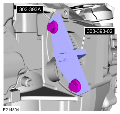
Install Special Service Tool: 303-393-02
Adapter for 303-393.
, 303-393A
Locking Tool, Flywheel.
-
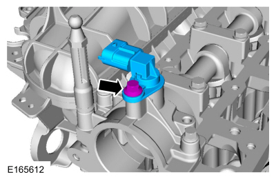
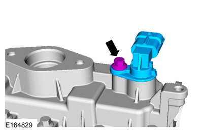
NOTE:
The O-ring seal is to be reused unless damaged.
-
Torque:
84 lb.in (9.5 Nm)
-
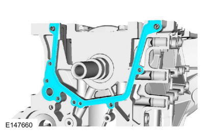
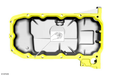
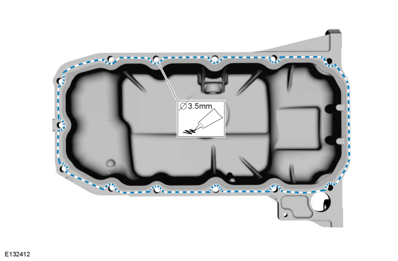
Clean and prepare the RTV sealing surface.
Refer to: RTV Sealing Surface Cleaning and Preparation (303-00 Engine System - General Information, General Procedures).
-
Clean and prepare the RTV sealing surface.
Refer to: RTV Sealing Surface Cleaning and Preparation (303-00 Engine System - General Information, General Procedures).
-
Clean and prepare the RTV sealing surface.
Refer to: RTV Sealing Surface Cleaning and Preparation (303-00 Engine System - General Information, General Procedures).
-
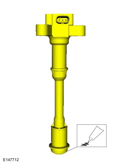
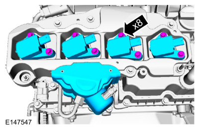
Install the following items:
-
NOTE:
The component must be installed within 5 minutes of applying the sealant.
Material: Motorcraft® High Performance Engine RTV Silicone
/ TA-357
(WSE-M4G323-A6)
-
Remove the following items:
-
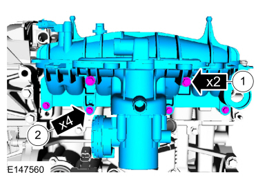
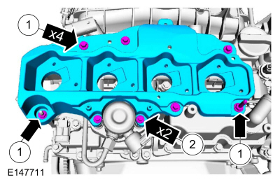
NOTE:
Only tighten the bolts finger tight at this stage.
-
Torque:
Stage 1:
1 - 13:
89 lb.in (10 Nm)
Stage 2:
1 - 13:
168 lb.in (19 Nm)
-
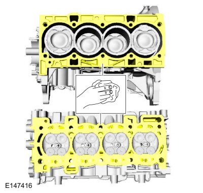
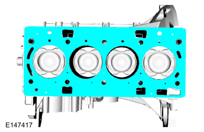
NOTICE:
Do not use metal scrapers, wire brushes, power abrasive
discs or other abrasive means to clean the sealing surfaces. These tools
cause scratches and gouges that make leak paths. Use a plastic scraping
tool to remove all traces of the head gasket.
NOTE:
If there is no residual gasket material present, metal
surface prep can be used to clean and prepare the surfaces.
Material: Motorcraft® Metal Surface Prep Wipes
/ ZC-31-B
-
-
-
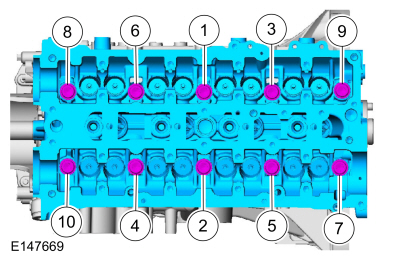
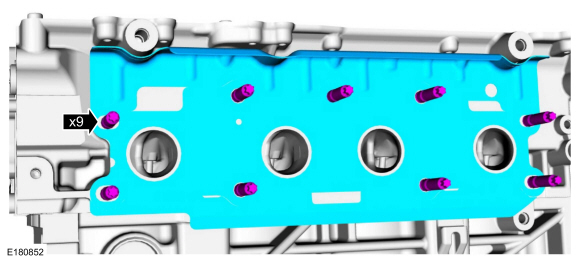
NOTE:
The cylinder head bolts are torque-to-yield and must not be reused. New cylinder head bolts must be installed.
NOTE:
Make sure that no fluids are present in the cylinder head bolt threaded bores.
Torque:
Stage 1:
44 lb.in (5 Nm)
Stage 2:
133 lb.in (15 Nm)
Stage 3:
26 lb.ft (35 Nm)
Stage 4:
90°
Stage 5:
Tighten an additional::
90°
-
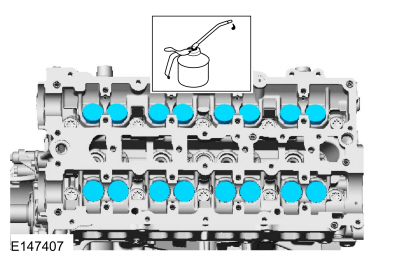
Material: Engine Oil - SAE 5W-20 - Synthetic Blend Motor Oil
/ XO-5W20-Q1SP
(WSS-M2C945-B1)
-
Material: Motorcraft® Metal Surface Prep Wipes
/ ZC-31-B
-
Material: Motorcraft® Metal Surface Prep Wipes
/ ZC-31-B
-
NOTICE:
If any new parts are being installed (cylinder head,
valves, tappets, camshafts) it is necessary to check the valve
clearance, follow the next 10 steps exactly or serious damage to the
engine may occur. If the original parts are being installed it is not
necessary to check the valve clearance so proceed to step 68.
Place a paint mark on the crankshaft at the 12 o'clock position.
-
Remove Special Service Tool: 303-393A
Locking Tool, Flywheel.
, 303-393-02
Adapter for 303-393.
-
Remove Special Service Tool: 303-748
Locking Tool, Crankshaft.
-
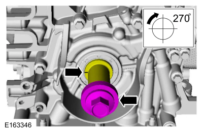
NOTE:
Rotating the crankshaft will position all of the pistons
below the deck of the cylinder block and allow the camshafts to be
installed and the valve clearance checked without the possibility of
damage to the valves or pistons.
Using the crankshaft bolt and washer, rotate the crankshaft
clockwise 270 degrees until the paint mark is at the 9 o'clock position.
 |
|
-
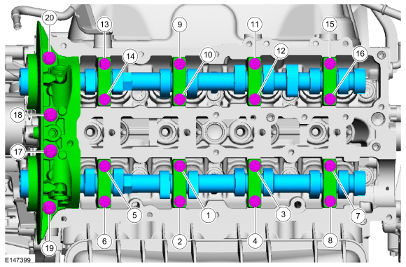
NOTICE:
Failure to follow the camshaft tightening procedure can result in damage to the camshafts.
NOTE:
Make sure that the components are installed to the location and orientation noted before removal.
NOTE:
Make sure that the mating faces are clean and free of foreign material.
NOTE:
Apply clean engine oil to the bearing surfaces of the camshafts, camshaft bearing caps and the VCT bridge.
Tighten the bolts evenly, half a turn at a time, until the camshaft
bearing caps and the VCT bridge are seated against the cylinder head.
Material: Engine Oil - SAE 5W-20 - Synthetic Blend Motor Oil
/ XO-5W20-Q1SP
(WSS-M2C945-B1)
Torque:
Stage 1:
Tighten bolts 1 through 16 to::
62 lb.in (7 Nm)
Stage 2:
Tighten bolts 17 through 20 to::
89 lb.in (10 Nm)
Stage 3:
Tighten bolts 1 through 16 an additional::
45°
Stage 4:
Tighten bolts 17 and 18 an additional::
70°
Stage 5:
Tighten bolts 19 and 20 an additional::
53°
 |
|
-
-
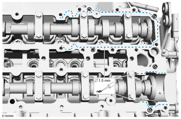
Using the flats of the camshaft, rotate the camshaft to
place the cam lobe at base circle, with the lobe pointed away from the
tappet.
-
Use a feeler gauge to measure the clearance of each valve and record its location.
Use the General Equipment: Feeler Gauge
-
Repeat to measure all of the lobe/tappet clearances.
-
NOTE:
Select tappets using this formula: ideal tappet
thickness = measured clearance + the existing tappet thickness - nominal
clearance. Select the closest tappet size to the ideal tappet thickness
available and mark the installation location.
NOTE:
The nominal clearance is:
-
intake: 0.0118 in (0.3 mm)
-
exhaust: 0.0157 in (0.4 mm)
NOTE:
The acceptable clearances after being fully installed are:
-
intake: 0.010–0.014 in (0.255–0.345 mm)
-
exhaust: 0.014–0.018 in (0.355–0.445 mm)
-
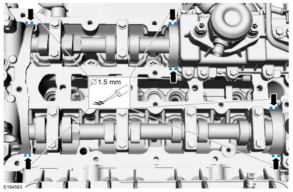
NOTICE:
Failure to follow the camshaft loosening procedure can result in damage to the camshafts.
NOTE:
Note the location and orientation of each camshaft
bearing cap and the position of the camshaft lobes on the No. 1 cylinder
for installation reference.
Loosen the camshaft bearing caps in sequence 2 turns at a
time until all tension is released from the camshaft bearing caps in
sequence shown.
-
Install Special Service Tool: 303-748
Locking Tool, Crankshaft.
-
NOTE:
Rotating the crankshaft will position the engine at TDC
and allow you to install the camshafts in the same position as noted
during the disassembly.
Rotate the crankshaft clockwise 90 degrees so the crankshaft contacts the Timing Peg, Crankshaft TDC 303-748.
-
If necessary, replace any tappets with the correct tappets selected during the valve clearance check.
-
NOTE:
Verify the crankshaft contacts the Timing Peg and the engine is still at TDC
Install Special Service Tool: 303-393A
Locking Tool, Flywheel.
, 303-393-02
Adapter for 303-393.
-
-
NOTE:
Make sure that the mating faces are clean and free of foreign material.
NOTE:
The VCT bridge must be installed within 5 minutes of applying the gasket maker.
Material: Flange Sealant
/ CU7Z-19B508-A
(WSS-M2G348-A11)
-
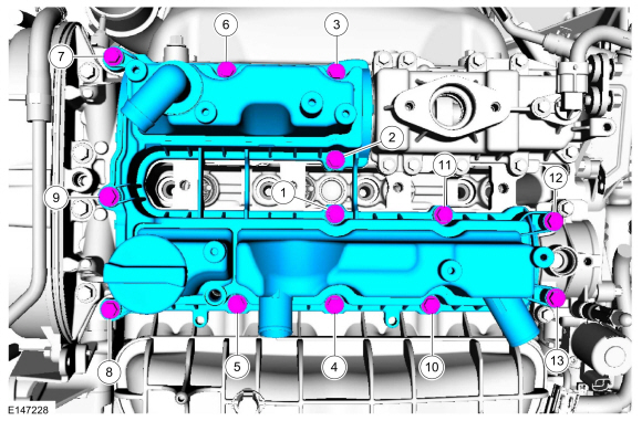
NOTICE:
Failure to follow the camshaft tightening procedure can result in damage to the camshafts.
NOTE:
Make sure that the components are installed to the location and orientation noted before removal.
NOTE:
Make sure that the mating faces are clean and free of foreign material.
NOTE:
Make sure that new bolts are installed.
NOTE:
Apply clean engine oil to the bearing surfaces of the camshafts, camshaft bearing caps and the VCT bridge.
Tighten the bolts evenly, half a turn at a time, until the camshaft
bearing caps and the VCT bridge are seated against the cylinder head.
Torque:
Stage 1:
1 - 16:
62 lb.in (7 Nm)
Stage 2:
17 - 20:
89 lb.in (10 Nm)
Stage 3:
1 - 16:
45°
Stage 4:
17 and 19:
70°
Stage 5:
18 and 20:
53°
-
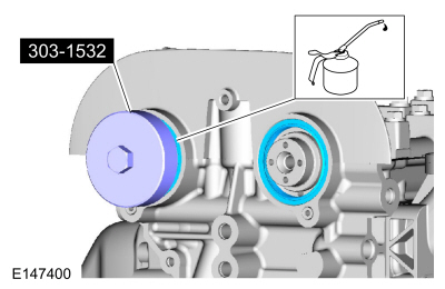
Use Special Service Tool: 303-1532
Installer, Camshaft Seal.
Material: Engine Oil - SAE 5W-20 - Synthetic Blend Motor Oil
/ XO-5W20-Q1SP
(WSS-M2C945-B1)
-
NOTE:
It may be necessary to use an open-ended wrench to turn the camshafts by the hexagon to align the camshafts.
Install Special Service Tool: 303-1552
Alignment Tool, Camshaft.
-
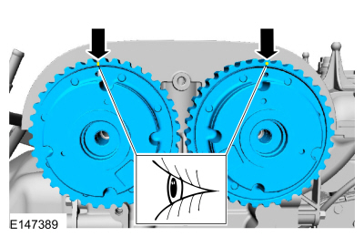
12 o'clock position.
-
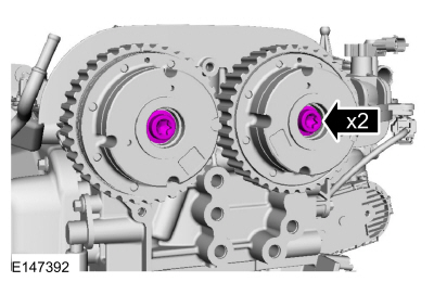
NOTE:
The timing mark of each VCT unit must be at the 12 o'clock position.
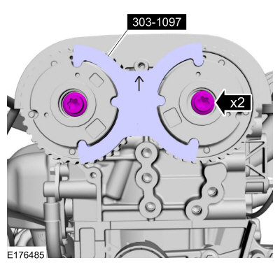
NOTE:
Use an open-ended wrench to hold the camshafts by the hexagon to prevent the camshafts from turning.
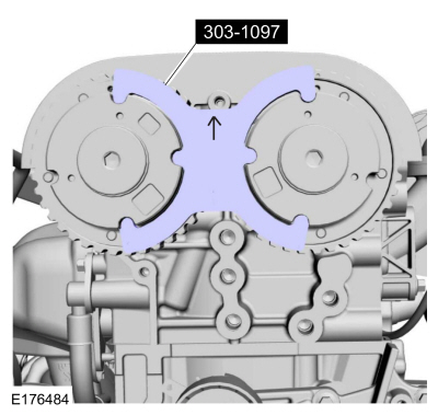
Install Special Service Tool: 303-1097
Locking Tool, Variable Camshaft Timing Oil Control Unit.
Torque:
18 lb.ft (25 Nm)
-
Remove Special Service Tool: 303-1097
Locking Tool, Variable Camshaft Timing Oil Control Unit.
-
Remove Special Service Tool: 303-1552
Alignment Tool, Camshaft.
-
NOTE:
Use an open-ended wrench to hold the camshafts by the hexagon to prevent the camshafts from turning.
Tighten an additional:
Torque:
75°
-
The special tool can only be installed if the valve timing is correct.
Install Special Service Tool: 303-1552
Alignment Tool, Camshaft.
-
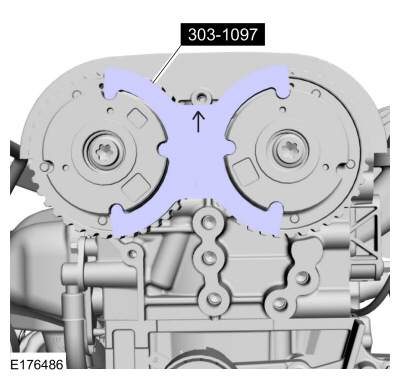
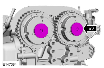
NOTE:
The timing mark of each VCT unit must be at the 12 o'clock position.
If the special tools cannot be installed, repeat the adjustment according to the preceding steps.
Install Special Service Tool: 303-1097
Locking Tool, Variable Camshaft Timing Oil Control Unit.
-
Remove Special Service Tool: 303-1097
Locking Tool, Variable Camshaft Timing Oil Control Unit.
-
Remove Special Service Tool: 303-1552
Alignment Tool, Camshaft.
-
NOTE:
Use an open-ended wrench to hold the camshafts by the hexagon to prevent the camshafts from turning.
Torque:
142 lb.in (16 Nm)
-
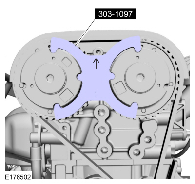
NOTE:
The timing mark of each VCT unit must be at the 12 o'clock position.
Install Special Service Tool: 303-1097
Locking Tool, Variable Camshaft Timing Oil Control Unit.
-
NOTE:
Make sure that the mating faces are clean and free of foreign material.
-
Torque:
Stage 1:
53 lb.in (6 Nm)
Stage 2:
89 lb.in (10 Nm)
-
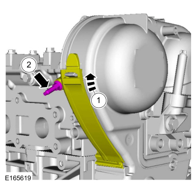
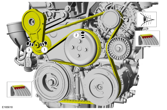
 WARNING:
The timing belt tensioner spring is under load. Extra
care must be taken at all times when handling the tensioner. Failure to
follow this instruction may result in personal injury.
WARNING:
The timing belt tensioner spring is under load. Extra
care must be taken at all times when handling the tensioner. Failure to
follow this instruction may result in personal injury.
Torque:
18 lb.ft (25 Nm)
-
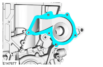
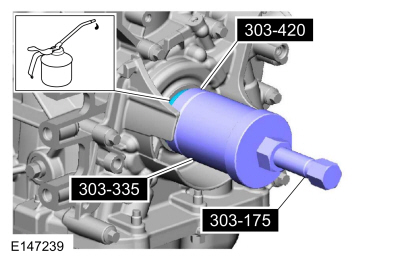
Make sure that the mating faces are clean and free of foreign material.
Use Special Service Tool: 303-175
(T82L-6316-A)
Installer, Crankshaft Vibration Damper.
, 303-335
(T88T-6701-A)
Installer, Front Cover Oil Seal.
, 303-420
(T92P-6701-BH)
Installer, Crankshaft Front Oil Seal.
Material: Engine Oil - SAE 5W-20 - Synthetic Blend Motor Oil
/ XO-5W20-Q1SP
(WSS-M2C945-B1)
-
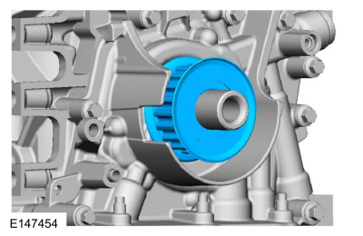
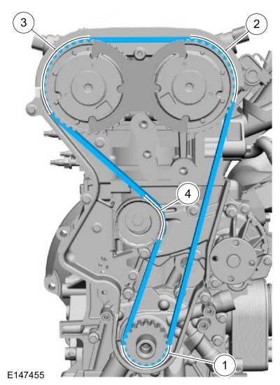
NOTE:
Before installation, clean and inspect the sprocket for
any damage. If damage is evident, replace the sprocket. If no damage,
the sprocket is to be reused.
-
-
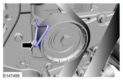
WARNING:
The timing belt tensioner spring is under load. Extra
care must be taken at all times when handling the tensioner. Failure to
follow this instruction may result in personal injury.
Remove the holding pin.
-
-
-
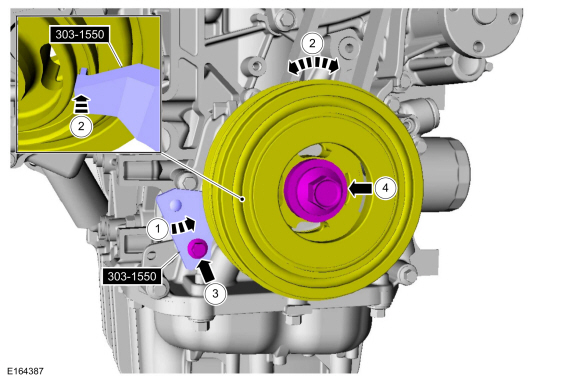
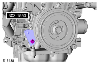
Install Special Service Tool: 303-1550
Alignment Tool, Crankshaft Vibration Damper.
-
Rotate crankshaft pulley to align the Special Tool:
Use Special Service Tool: 303-1550
Alignment Tool, Crankshaft Vibration Damper.
-
Finger tight at this stage.
-
Using a new bolt, finger tight at this stage.
-
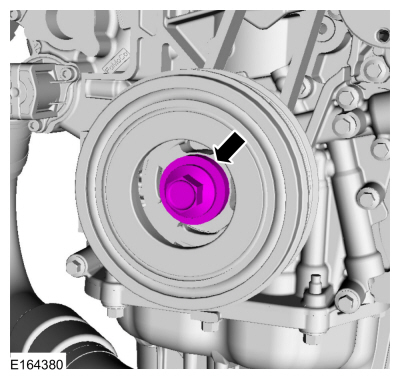
Torque:
Stage 1:
74 lb.ft (100 Nm)
Stage 2:
90°
Stage 3:
Wait 2 s
Stage 4:
Tighten an additional::
15°
-
Remove Special Service Tool: 303-1550
Alignment Tool, Crankshaft Vibration Damper.
-
Remove Special Service Tool: 303-748
Locking Tool, Crankshaft.
-
Remove Special Service Tool: 303-1097
Locking Tool, Variable Camshaft Timing Oil Control Unit.
-
Remove Special Service Tool: 303-393-02
Adapter for 303-393.
, 303-393A
Locking Tool, Flywheel.
-
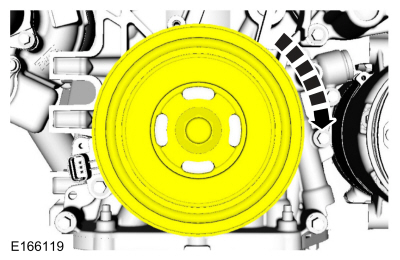
NOTE:
Only rotate the crankshaft in a clockwise direction.
Rotate about 1 3/4 turns.
-
Install Special Service Tool: 303-748
Locking Tool, Crankshaft.
-
NOTE:
Only rotate the crankshaft in a clockwise direction.
Rotate the crankshaft slowly clockwise until the crankshaft
balance weight is up against the crankshaft locking tool. The engine is
now at TDC .
-
NOTE:
The timing mark of each VCT unit must be at the 12 o'clock position.
NOTE:
It may necessary to rotate the camshafts slightly to install the special tool.
If the special tool cannot be installed, repeat the adjustment according to the preceding steps.
Install Special Service Tool: 303-1097
Locking Tool, Variable Camshaft Timing Oil Control Unit.
-
Remove Special Service Tool: 303-1097
Locking Tool, Variable Camshaft Timing Oil Control Unit.
-
Remove Special Service Tool: 303-748
Locking Tool, Crankshaft.
-
Torque:
177 lb.in (20 Nm)
-
Torque:
89 lb.in (10 Nm)
-
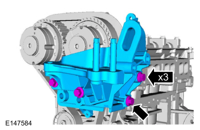
NOTE:
There are different length of bolts noted in disassembly.
Torque:
41 lb.ft (55 Nm)
-
-
Torque:
89 lb.in (10 Nm)
-
Finger tight.
-
Finger tight.
-
Torque:
89 lb.in (10 Nm)
-
If equipped with block heater.
Torque:
27 lb.in (3 Nm)
-
Torque:
89 lb.in (10 Nm)
-
-
Tighten the fasteners to specification a second time.
Torque:
15 lb.ft (21 Nm)
-
Torque:
177 lb.in (20 Nm)
-
Torque:
177 lb.in (20 Nm)
-
Torque:
18 lb.ft (25 Nm)
-
-
Tighten the fasteners to specification a second time.
Torque:
18 lb.ft (25 Nm)
-
Material: Engine Oil - SAE 5W-20 - Synthetic Blend Motor Oil
/ XO-5W20-Q1SP
(WSS-M2C945-B1)
-
-
Torque:
19 lb.ft (26 Nm)
-
Torque:
84 lb.in (9.5 Nm)
-
Material: Engine Oil - SAE 5W-20 - Synthetic Blend Motor Oil
/ XO-5W20-Q1SP
(WSS-M2C945-B1)
-
Torque:
84 lb.in (9.5 Nm)
-
-
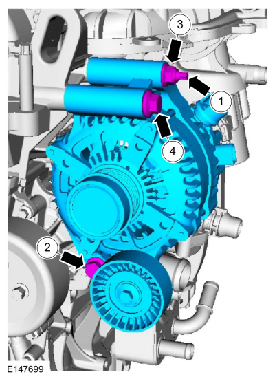
Torque:
159 lb.in (18 Nm)
-
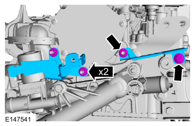
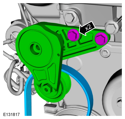
Torque:
21 lb.ft (28 Nm)
-
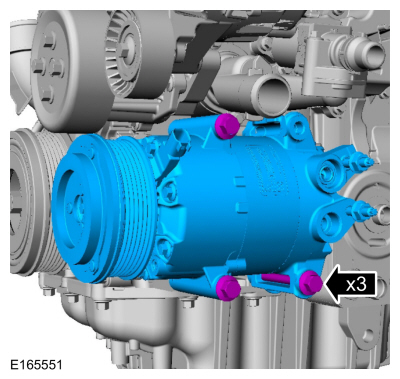
Torque:
17 lb.ft (23 Nm)
-
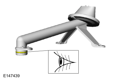
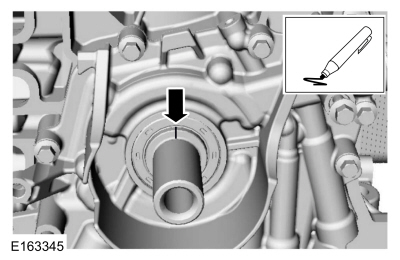
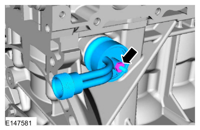
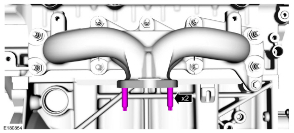
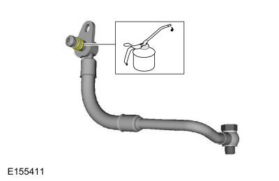
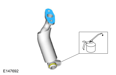
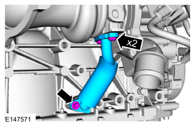
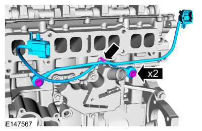
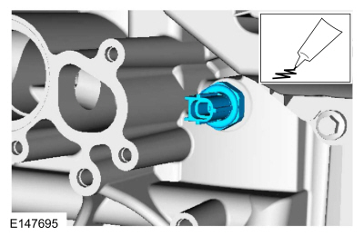
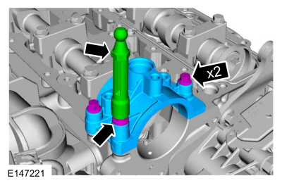
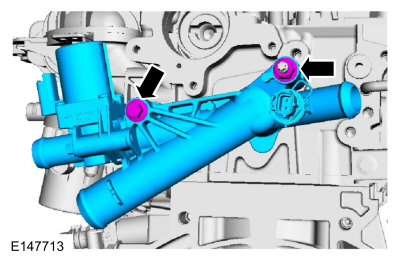
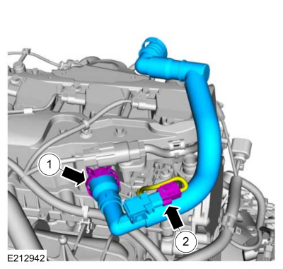
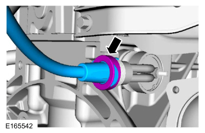
NOTE:
Lubricate the spigot with clean engine oil.
.
Material: Engine Oil - SAE 5W-20 - Synthetic Blend Motor Oil
/ XO-5W20-Q1SP
(WSS-M2C945-B1)
-
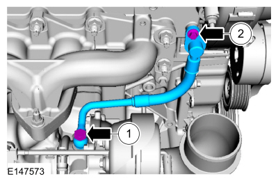
-
Push the spigot into the engine block.
-
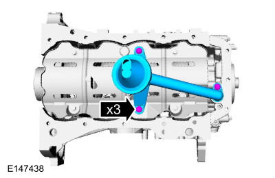
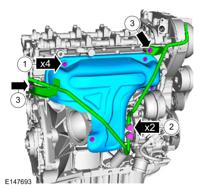
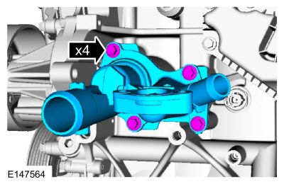
Tighten bolts 1, 2 and 3.
Torque:
49 lb.in (5.5 Nm)
-
Tighten bolts 4, 5, 6, 7 and 8.
Torque:
49 lb.in (5.5 Nm)
-
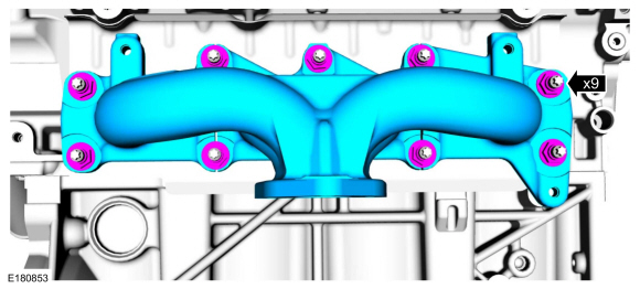
Tighten all bolts in sequence.
Torque:
84 lb.in (9.5 Nm)
-
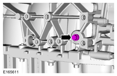
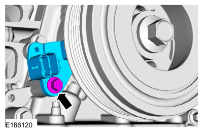
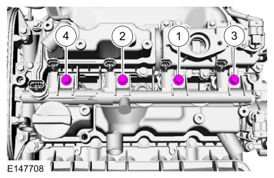
NOTE:
The head of the KS should not touch any other component.
NOTE:
The LH
KS must be at the 10 o'clock position and the RH
KS must be at the 2 o'clock position.
Torque:
159 lb.in (18 Nm)
-
Material: Motorcraft® Thread Sealant with PTFE
/ TA-24-B
(WSK-M2G350-A2)
Torque:
159 lb.in (18 Nm)
-
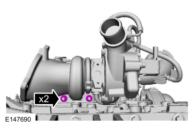
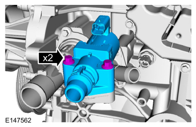
Torque:
80 lb.in (9 Nm)
-
Torque:
89 lb.in (10 Nm)
-
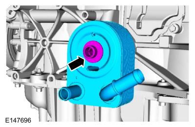
NOTICE:
A new oil cooler must be installed or severe damage to the engine can occur.
Torque:
41 lb.ft (55 Nm)
-
NOTE:
There are different length of bolts noted in disassembly.
-
Torque:
150 lb.in (17 Nm)
-
Torque:
89 lb.in (10 Nm)
-
NOTICE:
Do not use metal scrapers, wire brushes, power abrasive
discs or other abrasive means to clean the sealing surfaces. These tools
cause scratches and gouges which make leak paths.
Make sure that the mating faces are clean and free of foreign material.
Material: Motorcraft® Metal Surface Prep Wipes
/ ZC-31-B
-
NOTICE:
Do not use metal scrapers, wire brushes, power abrasive
discs or other abrasive means to clean the sealing surfaces. These tools
cause scratches and gouges which make leak paths.
Make sure that the mating faces are clean and free of foreign material.
Material: Motorcraft® Metal Surface Prep Wipes
/ ZC-31-B
-
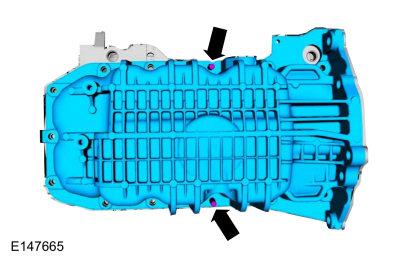
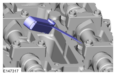
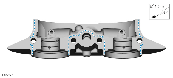
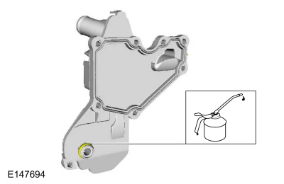
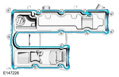
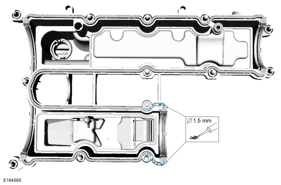
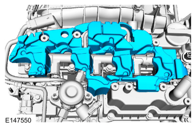
NOTE:
The components must be installed within 5 minutes of applying the sealant.
Material: Flange Sealant
/ CU7Z-19B508-A
(WSS-M2G348-A11)
-
Torque:
89 lb.in (10 Nm)
-
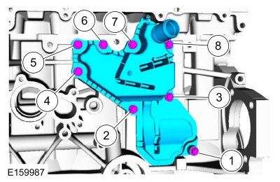
NOTE:
Use a new O-ring seal.
Tighten bolts 1 through 10 to:
Torque:
Stage 1:
27 lb.in (3 Nm)
Stage 2:
80 lb.in (9 Nm)
Stage 3:
97 lb.in (11 Nm)
Stage 4:
Tighten bolts 1, 2, 5, 6, 7, 8, 9 and 10 to::
124 lb.in (14 Nm)
-
Torque:
80 lb.in (9 Nm)
-
Torque:
80 lb.in (9 Nm)
-
-
NOTE:
The components must be installed within 5 minutes of applying the sealant.
Material: Flange Sealant
/ CU7Z-19B508-A
(WSS-M2G348-A11)
-
Material: Flange Sealant
/ CU7Z-19B508-A
(WSS-M2G348-A11)
-
Torque:
Stage 1:
44 lb.in (5 Nm)
Stage 2:
80 lb.in (9 Nm)
Stage 3:
89 lb.in (10 Nm)
-
NOTE:
A clean working environment is essential to prevent dirt or foreign material contamination.
NOTE:
Make sure to thoroughly clean any residual fuel or
foreign material from the cylinder head, block and the general
surrounding area of the fuel rails and injectors.
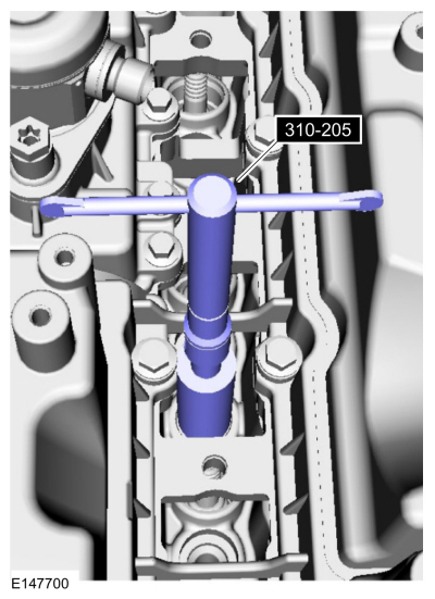
NOTE:
Do not use compressed air to clean the tip of the fuel injector.
NOTE:
Do not use a brush to clean the tip of the fuel injector.
Use Special Service Tool: 310-205
Fuel Injector Brush.
-
-
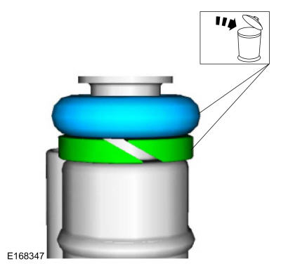
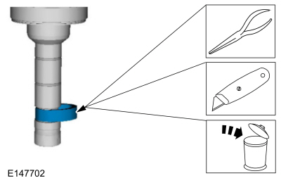
NOTICE:
Use care when removing the lower Teflon® seals, not to scratch, nick or gouge the fuel injectors.
NOTICE:
Do not attempt to cut the lower Teflon® seal without
first pulling it away from the fuel injector or damage to the injector
may occur.
NOTE:
-
Pull the lower Teflon® seal away from the injector.
-
Carefully cut and discard the lower fuel injector Teflon® seals.
-
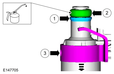
NOTICE:
Do not lubricate the new lower Teflon® fuel injector seals.
-
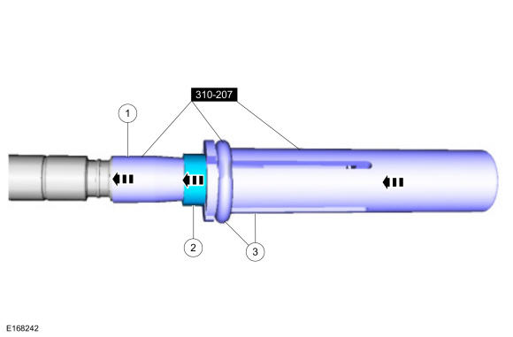
Use Special Service Tool: 310-207
Installer, Fuel Injector Seal Assembly.
-
NOTICE:
Once the Teflon® seal is installed on the Teflon®
Seal Guide, it should immediately be installed onto the fuel injector to
avoid excessive expansion of the Teflon® seal.
NOTE:
Make sure that new lower fuel injector Teflon® seals are installed.
-
Using the Pusher Tool, slide the Teflon® seals off of
the Teflon® Seal Guide and into the groove on the fuel injectors.
Use Special Service Tool: 310-207
Installer, Fuel Injector Seal Assembly.
 |
|
-
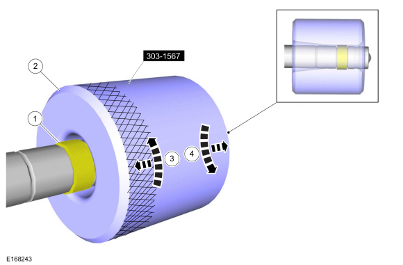
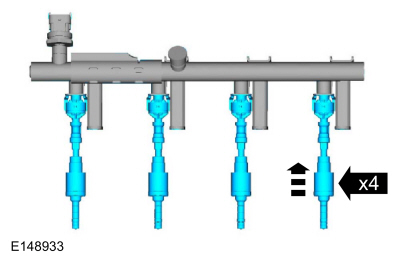
NOTICE:
Install the fuel injectors into the cylinder head within
15 minutes of sizing the seals due to Teflon® seal expansion.
NOTE:
Make sure the Teflon® seal is fully seated in the groove on the fuel injector before sizing the Teflon® seal.
-
Some Teflon® seal massaging with your fingers before the
Teflon® seal sizer tool is installed will aid in installing the Teflon®
seal sizer tool.
-
Position the Teflon® seal sizer tool with the larger
opening towards the Teflon® seal. Push while turning the Teflon® seal
sizer tool 180 degrees.
Use Special Service Tool: 303-1567
Sizer, Teflon Seal.
-
Once the Teflon® seal sizer tool is installed, check and
make sure the Teflon® seal is in the sizing portion of the Teflon® seal
sizer tool. After one minute, turn the Teflon® seal sizer tool back 180
degrees and remove.
 |
|
-
NOTICE:
Use fuel injector O-ring seals that are made of special
fuel-resistant material. The use of ordinary O-ring seals may cause the
fuel system to leak. Do not reuse the O-ring seals.
NOTE:
Do not lubricate the new lower Teflon® fuel injector seals.
Material: Engine Oil - SAE 5W-20 - Synthetic Blend Motor Oil
/ XO-5W20-Q1SP
(WSS-M2C945-B1)
-
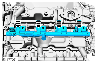
NOTE:
The anti-rotation finger of the fuel injector clip must slip into the groove of the fuel rail cup.
NOTE:
The fuel rail pressure sensor must be replaced if it is removed from the fuel rail.
-
NOTE:
Take extra care when handling the components.
Only use moderate force.
-
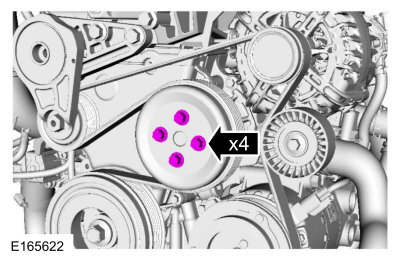
Install the 4 bolts finger tight.
Torque:
Stage 1:
44 lb.in (5 Nm)
Stage 2:
17 lb.ft (23 Nm)
-
Material: Engine Oil - SAE 5W-20 - Synthetic Blend Motor Oil
/ XO-5W20-Q1SP
(WSS-M2C945-B1)
-
NOTE:
Install all the bolts finger tight before final tightening.
-
Material: Engine Oil - SAE 5W-20 - Synthetic Blend Motor Oil
/ XO-5W20-Q1SP
(WSS-M2C945-B1)
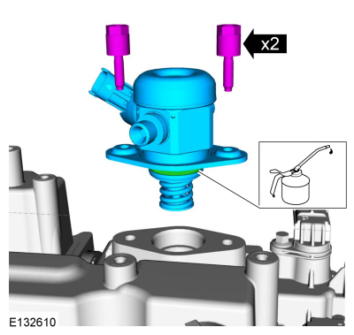
-
Install the fuel injection pump and loosely install the 2
fuel injection pump bolts, alternately tighten each bolt one half of a
revolution until seated.
Torque:
115 lb.in (13 Nm)
-
NOTE:
Make sure that a new component is installed.
NOTE:
Calculate the correct torque wrench setting for the following torque. Refer to Torque Wrench Adapter Formulas.
-
Torque:
62 lb.in (7 Nm)
-
Torque:
Stage 1:
Using a torque adapter, tighten to::
15 lb.ft (21 Nm)
Stage 2:
Wait 5 min
Stage 3:
Using a torque adapter, tighten to::
15 lb.ft (21 Nm)
-
-
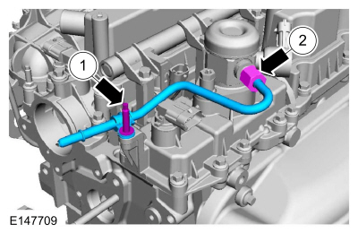
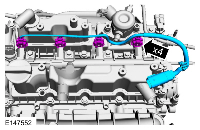
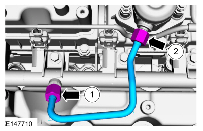
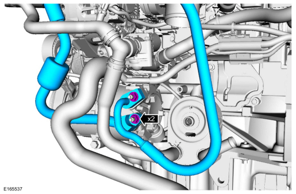
NOTE:
Make sure that a new component is installed.
NOTE:
Only tighten the 2 high pressure fuel tube flare nuts finger tight at this stage.
NOTE:
Calculate the correct torque wrench setting for the following torque. Refer to Torque Wrench Adapter Formulas.
Torque:
Stage 1:
Using a torque adapter, tighten to::
15 lb.ft (21 Nm)
Stage 2:
Wait 5 min
Stage 3:
Using a torque adapter, tighten to::
15 lb.ft (21 Nm)
-
-
-
Torque:
89 lb.in (10 Nm)
-
Torque:
53 lb.in (6 Nm)
-
Material: Motorcraft® Silicone Brake Caliper Grease and Dielectric Compound
/ XG-3-A
(ESA-M1C200-A)
(ESE-M1C171-A)
-
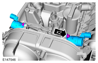
NOTE:
When removing or installing the fuel injection pump
noise insulator, spreading the openings will reduce the risk of damage.
Torque:
89 lb.in (10 Nm)
-
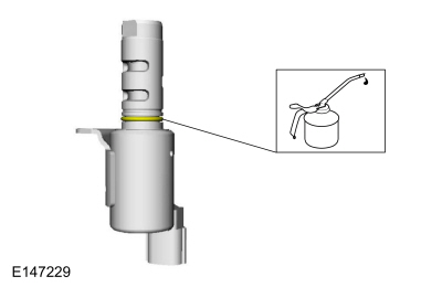
NOTE:
The O-ring seals are to be reused unless damaged.
Material: Engine Oil - SAE 5W-20 - Synthetic Blend Motor Oil
/ XO-5W20-Q1SP
(WSS-M2C945-B1)
-
Torque:
71 lb.in (8 Nm)
-
Torque:
159 lb.in (18 Nm)
-
NOTE:
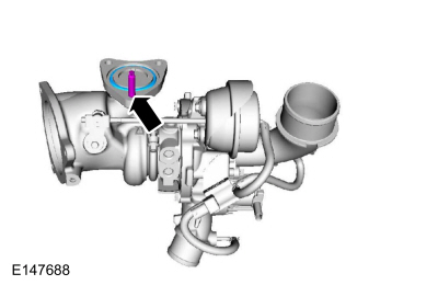
Make sure that the mating faces are clean and free of foreign material.
-
Material: Flange Sealant - Anaerobic
/ Loctite® 51031
(WSK-M2G348-A7)
-
-
Torque:
89 lb.in (10 Nm)
-
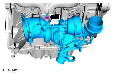
Torque:
168 lb.in (19 Nm)
-
Torque:
89 lb.in (10 Nm)
-
-
Torque:
89 lb.in (10 Nm)
-
Torque:
35 lb.ft (48 Nm)
-
Torque:
35 lb.ft (48 Nm)
-
Torque:
35 lb.ft (48 Nm)
-
Torque:
18 lb.ft (25 Nm)
-
Torque:
35 lb.ft (48 Nm)
-
-
Torque:
18 lb.ft (24 Nm)
-
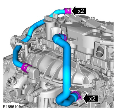
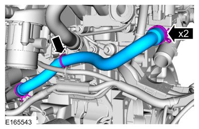
Use the General Equipment: Hose Clamp Remover/Installer
-
Torque:
89 lb.in (10 Nm)
-
-
-
-
Torque:
71 lb.in (8 Nm)
-
-
-
Torque:
133 lb.in (15 Nm)
-
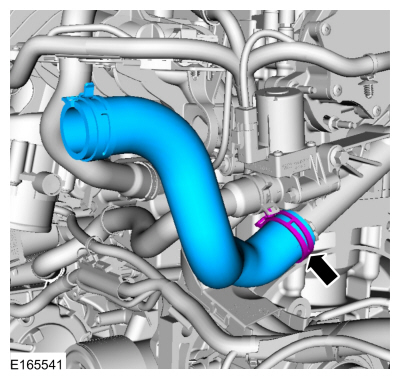
Use the General Equipment: Hose Clamp Remover/Installer
-
Use the General Equipment: Hose Clamp Remover/Installer
-
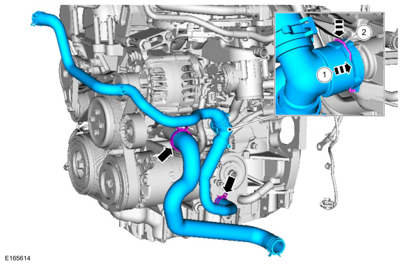
Use the General Equipment: Hose Clamp Remover/Installer
-
Use the General Equipment: Hose Clamp Remover/Installer
-
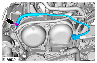
Use the General Equipment: Hose Clamp Remover/Installer
-
-
Use the General Equipment: Hose Clamp Remover/Installer
-
If equipped.
-
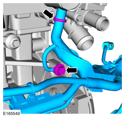
NOTE:
Install new O-ring seals and gasket seals.
Torque:
133 lb.in (15 Nm)
-
If equipped with block heater.
-
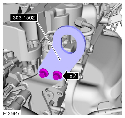
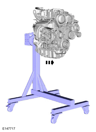
Install Special Service Tool: 303-1502
Lifting Device Engine.
-
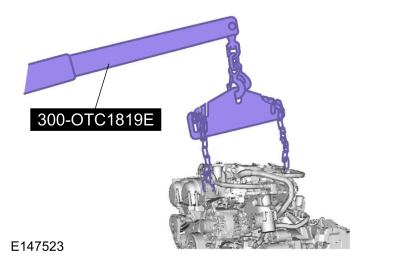
Install Special Service Tool: 300-OTC1819E
2,200# Floor Crane, Fold Away.
-
Remove from engine stand.
-
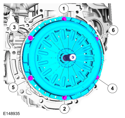
NOTICE:
Do not breathe dust or use compressed air to blow dust
from storage containers or friction components. Remove dust using
government-approved techniques. Friction component dust may be a cancer
and lung disease hazard. Exposure to potentially hazardous components
may occur if dusts are created during repair of friction components,
such as brake pads and clutch discs. Exposure may also cause irritation
to skin, eyes and respiratory tract, and may cause allergic reactions
and/or may lead to other chronic health effects. If irritation persists,
seek medical attention or advice. Failure to follow these instructions
may result in serious personal injury.
Using a clutch aligner, centralize the clutch disc to the clutch pressure plate.
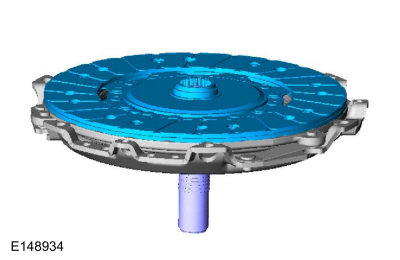 |
|
-
NOTICE:
Do not breathe dust or use compressed air to blow dust
from storage containers or friction components. Remove dust using
government-approved techniques. Friction component dust may be a cancer
and lung disease hazard. Exposure to potentially hazardous components
may occur if dusts are created during repair of friction components,
such as brake pads and clutch discs. Exposure may also cause irritation
to skin, eyes and respiratory tract, and may cause allergic reactions
and/or may lead to other chronic health effects. If irritation persists,
seek medical attention or advice. Failure to follow these instructions
may result in serious personal injury.
Torque:
21 lb.ft (29 Nm)
Materials
Name
Specification
Engine Oil - SAE 5W-20 - Synthetic Blend Motor OilXO-5W20-Q1SP
WSS-M2C945-B1
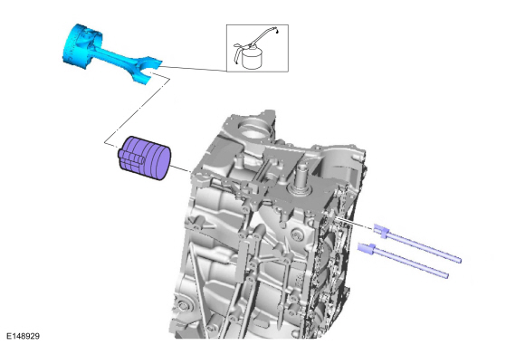
DISASSEMBLY
Remove and discard the piston rings...
Special Tool(s) /
General Equipment
205-461Protector, Differential Oil Seal (pair)TKIT-2000AP-FLM/LMTKIT-2002-F/FM
300-OTC1585AEPowertrain Lift
300-OTC1819E2,200# Floor Crane, Fold Away
303-1502Lifting Device EngineTKIT-2012A-FLTKIT-2012A-ROW
303-476
(T94P-9472-A)
Socket, Exhaust Gas Oxygen SensorTKIT-1994-LM/MTKIT-1994-FTKIT-1994-FLM/FM
..
Other information:
B00C2:11 and B00C2:12
Refer to Wiring Diagrams Cell 46 for schematic and connector information.
Normal Operation and Fault Conditions
The Belt Tension Sensor (BTS) operates in conjunction with the OCS . The OCSM
provides a reference voltage to the Belt Tension Sensor (BTS), which
changes as it passes through the sensor, based on how much tension is
applied to the safe..
Special Tool(s) /
General Equipment
211-001
(TOOL-3290-D)
Remover, Tie-Rod End
Removal
NOTICE:
Suspension fasteners are critical parts that affect
performance of vital components and systems. Failure of these fasteners
may result in major service expense. Use the same or equivalent parts if
replacement is necessary. Do not use a replacement part of lesser ..
Categories
Special Tool(s) /
General Equipment
Master Cylinder Bleeding Set
Bleeding
NOTICE:
If the fluid is spilled on the paintwork, the affected area must be immediately washed down with cold water.
Master Cylinder
NOTE:
When a new brake master cylinder has been installed, it
should be primed to prevent air from entering the system.
NOTE:
Make sure the area around the master cylinder cap is clean and free of foreign material.
Remove the brake fluid reservoir cap.
read more


 Piston. Disassembly and Assembly of Subassemblies
 Engine. Installation