Ford Fiesta: Engine - 1.6L EcoBoost (132kW/180PS) – Sigma / Engine. Installation
Ford Fiesta 2014 - 2019 Service Manual / Engine / Engine - 1.6L EcoBoost (132kW/180PS) – Sigma / Engine. Installation
Special Tool(s) / General Equipment
 |
205-461 Protector, Differential Oil Seal (pair) TKIT-2000AP-FLM/LM TKIT-2002-F/FM |
 |
300-OTC1585AE Powertrain Lift |
 |
300-OTC1819E 2,200# Floor Crane, Fold Away |
 |
303-1502 Lifting Device Engine TKIT-2012A-FL TKIT-2012A-ROW |
 |
303-476
(T94P-9472-A)
Socket, Exhaust Gas Oxygen Sensor TKIT-1994-LM/M TKIT-1994-F TKIT-1994-FLM/FM |
| Cable Ties | |
| Hose Clamp Remover/Installer | |
| Wooden Block | |
Materials
| Name | Specification |
|---|---|
| Motorcraft® High Temperature 4x4 Front Axle and Wheel Bearing Grease XG-11 |
WSS-M1C267-A1 |
| Engine Oil - SAE 5W-20 - Synthetic Blend Motor Oil XO-5W20-Q1SP |
WSS-M2C945-B1 |
| Motorcraft® High Temperature Nickel Anti-Seize Lubricant XL-2 |
- |
-
Lubricate the torque converter pilot hub with multi-purpose grease.
Material: Motorcraft® High Temperature 4x4 Front Axle and Wheel Bearing Grease / XG-11 (WSS-M1C267-A1)
 |
-
Align the engine to transmission and install the bolt.
Torque: 35 lb.ft (48 Nm)
 |
-
Install the engine to transmission bolts.
Torque: 35 lb.ft (48 Nm)
 |
-
Install the engine to transmission bolts.
Torque: 35 lb.ft (48 Nm)
 |
-
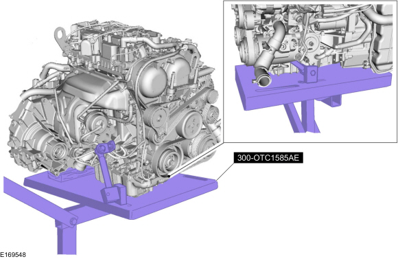
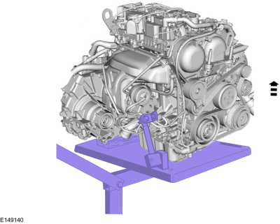
Install the engine on the table.
Install Special Service Tool: 300-OTC1585AE Powertrain Lift.
Use the General Equipment: Wooden Block
 |
-
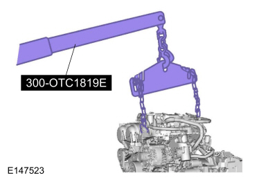
Remove the engine floor crane.
Remove Special Service Tool: 300-OTC1819E 2,200# Floor Crane, Fold Away.
 |
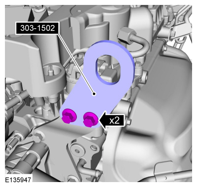
- Remove Special Service Tool: 303-1502 Lifting Device Engine.
 |
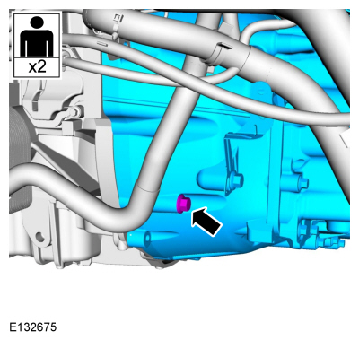
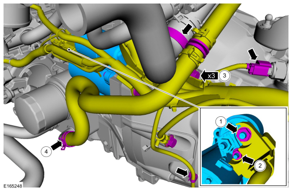
-
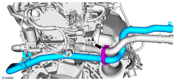
Install the coolant hose and attach the retainer.
 |
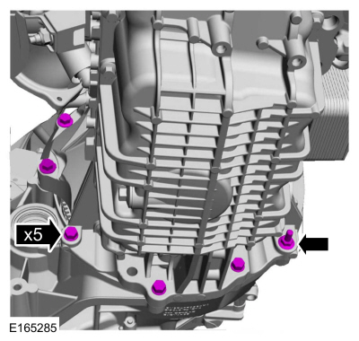
-
-
Install the starter motor and the bolts, position the
starter motor solenoid terminal wiring electrical connection and install
the nut.
Torque: 89 lb.in (10 Nm)
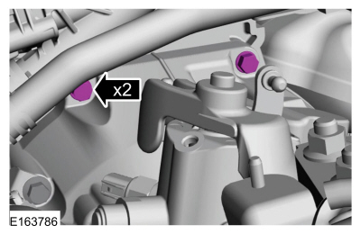
-
Install the solenoid terminal wiring electrical connection nut.
Torque: 89 lb.in (10 Nm)
-
Position the ground cable and install the bolt.
Torque: 35 lb.ft (48 Nm)
-
Install the coolant hose and the clamps, connect the electrical connector and the wiring harness retainer.
Use the General Equipment: Hose Clamp Remover/Installer
-
Install the starter motor and the bolts, position the
starter motor solenoid terminal wiring electrical connection and install
the nut.
 |
-
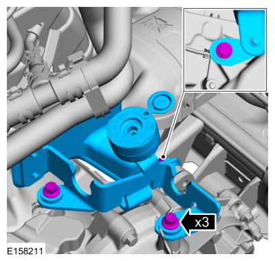
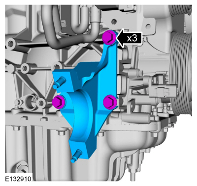
Install the bracket and the bolts.
Torque: 177 lb.in (20 Nm)
 |
-
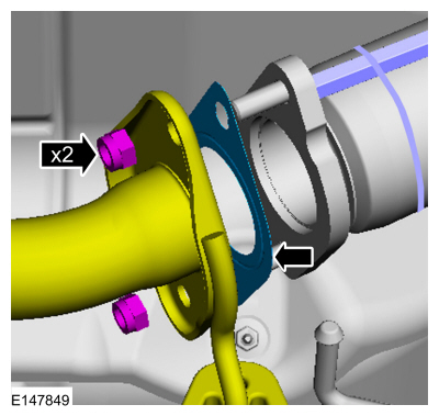
Install the new catalytic convertor gasket and loosely install the bolts.
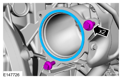 |
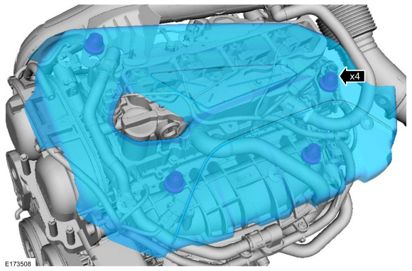
-
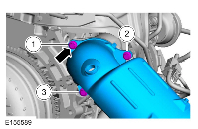
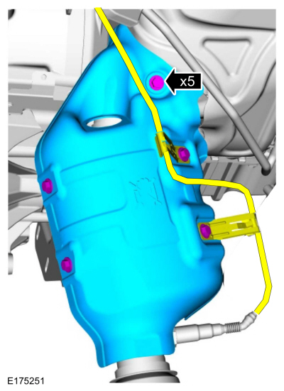
Install the catalytic converter on the loosely installed
bolts, install the remaining bolt and then tighten the bolts in the
sequence shown.
Torque: 18 lb.ft (25 Nm)
 |
-
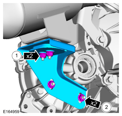
Install the catalytic converter mounting bracket and the nuts.
Torque: 18 lb.ft (24 Nm)
 |
-
Install the heat shield, position the clamp and install the bolts.
Torque: 89 lb.in (10 Nm)
 |
-
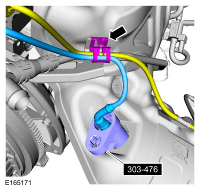
Using the special tool, install the HO2S . Attach the wiring harness retainer.
Use Special Service Tool: 303-476 (T94P-9472-A) Socket, Exhaust Gas Oxygen Sensor.
Material: Motorcraft® High Temperature Nickel Anti-Seize Lubricant / XL-2
Torque: 35 lb.ft (48 Nm)
 |
-
Connect the electrical connectors.
 |
-
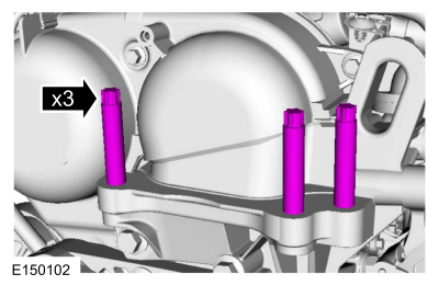
Tighten the engine mounting studs.
Torque: 89 lb.in (10 Nm)
 |
-
Using the powertrain lift, raise the powertrain into the vehicle.
 |
-
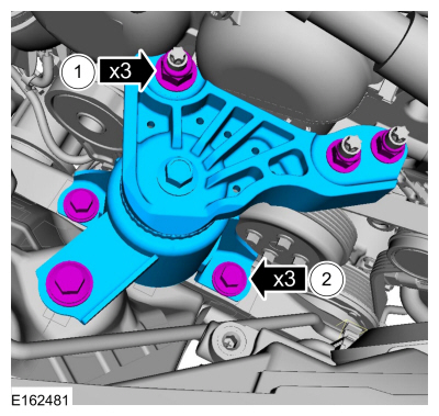
-
Install the engine mount and the nuts.
Torque: 59 lb.ft (80 Nm)
-
Install the bolts.
Torque: 35 lb.ft (48 Nm)
-
Install the engine mount and the nuts.
 |
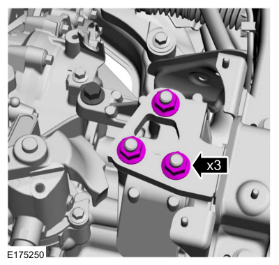
-
Install the nuts.
Torque: 92 lb.ft (125 Nm)
 |
-
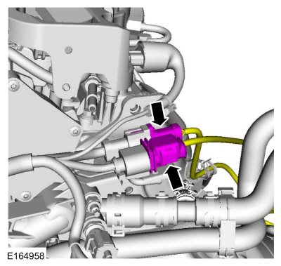
Using a new gasket, position the muffler inlet pipe and install the nuts.
Torque: 35 lb.ft (48 Nm)
 |
-
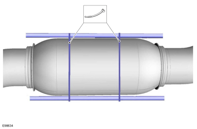
Remove the cable ties.
Use the General Equipment: Cable Ties
 |
-
Install the bracket and the bolts.
Torque: 35 lb.ft (48 Nm)
 |
-
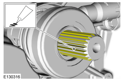
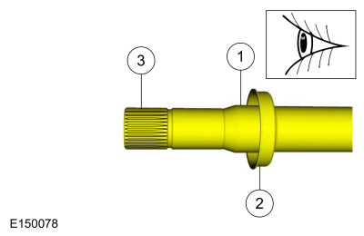
Clean and inspect the inner LH halfshaft splines and mating surfaces
 |
-
Replace the LH halfshaft seal.
Refer to: Halfshaft Seal LH (308-03B Manual Transmission - 6-Speed Manual Transmission – B6, Removal and Installation).
-
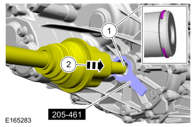
NOTE: Make sure a new circlip is installed.
Install a new LH halfshaft retaining circlip.
Remove Special Service Tool: 205-461 Protector, Differential Oil Seal (pair).
 |
-
NOTE: When seated correctly, the halfshaft bearing retainer circlip can be felt as it snaps into the differential side gear groove.
Install the shaft. Pull the halfshaft outward to make sure the circlip is locked.
 |
-
Clean and inspect the RH inner halfshaft splines and mating surfaces.
 |
-
Replace the RH halfshaft seal.
Refer to: Halfshaft Seal RH (308-03B Manual Transmission - 6-Speed Manual Transmission – B6, Removal and Installation).
-
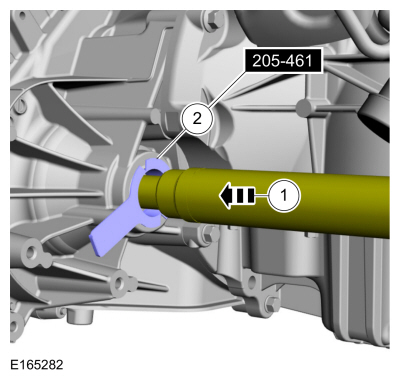
Remove the special tool before completely installing the RH halfshaft.
Remove Special Service Tool: 205-461 Protector, Differential Oil Seal (pair).
 |
-
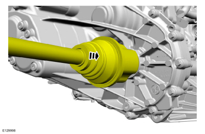
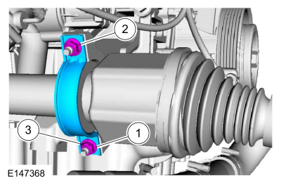
Install the RH halfshaft.
 |
-
Install the new halfshaft bearing retaining strap and the nuts.
Torque:
Stage 1: 44 lb.in (5 Nm)
Stage 2: 18 lb.ft (24 Nm)
 |
-
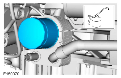
Lubricate and install the engine oil filter.
Material: Engine Oil - SAE 5W-20 - Synthetic Blend Motor Oil / XO-5W20-Q1SP (WSS-M2C945-B1)
Torque: 128 lb.in (14.5 Nm)
 |
-
Install the front subframe.
Refer to: Front Subframe (502-00 Uni-Body, Subframe and Mounting System, Removal and Installation).
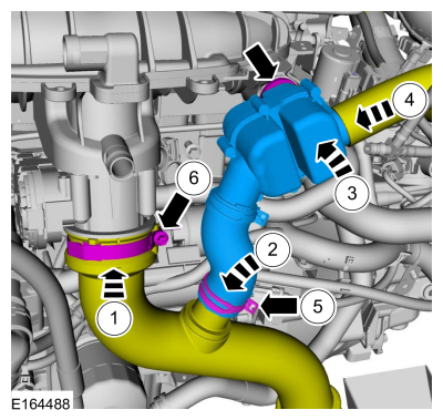
-
-
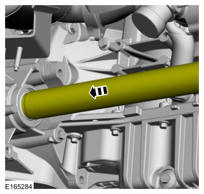
Install the TC outlet tube and tighten the clamps.
Torque: 44 lb.in (5 Nm)
-
Install the nuts.
Torque: 97 lb.in (11 Nm)
-
Install the TC outlet tube and tighten the clamps.
 |
-
Install the shield and the retainers.
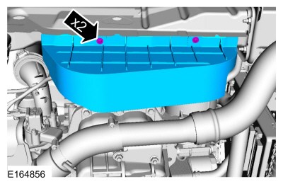 |
-
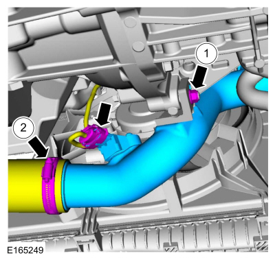
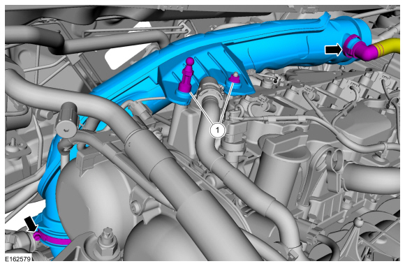
-
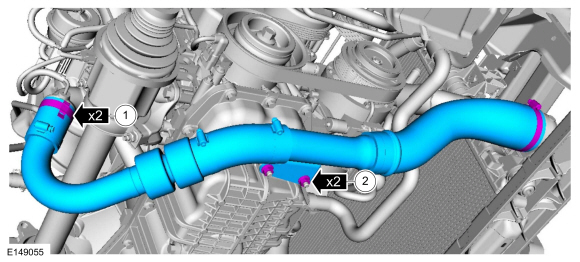
Install the CAC outlet pipe and the nut.
Torque: 97 lb.in (11 Nm)
-
Tighten the clamp and connect the electrical connector.
Torque: 44 lb.in (5 Nm)
-
Install the CAC outlet pipe and the nut.
 |
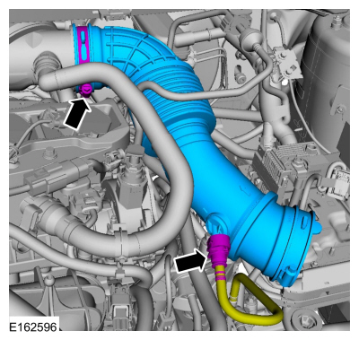
-
Connect the trottle body hose and tighten the clamp, install
the resonator assembly and the hose clamps and connect the hose.
Use the General Equipment: Hose Clamp Remover/Installer
Torque: 44 lb.in (5 Nm)
 |
-
Install the degas bottle.
Refer to: Degas Bottle (303-03B Engine Cooling - 1.6L EcoBoost (132kW/180PS) – Sigma, Removal and Installation).
-
NOTE: Install a new the O-ring seal and gasket seal.
Using a new O-ring, connect the A/C line and install the nut.
Torque: 133 lb.in (15 Nm)
 |
-
NOTE: Install a new the O-ring seal and gasket seal.
Using a new O-ring, connect the A/C line and install the nut.
Torque: 133 lb.in (15 Nm)
 |
-
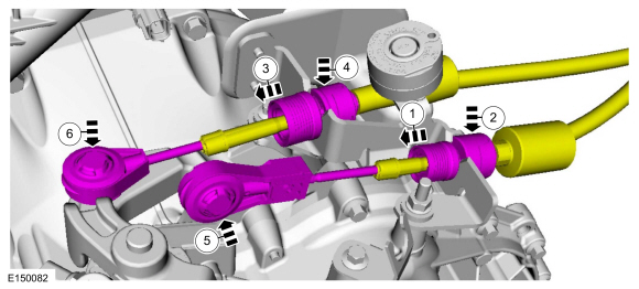
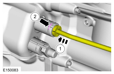
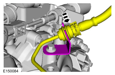
Connect the selector lever cables from the selector levers.
 |
-
Adjust the gearshift cable.
Refer to: Gearshift Cable Adjustment - 6-Speed Manual Transmission – B6 (308-06 Manual Transmission External Controls - 5-Speed Manual Transmission – B5/IB5/6-Speed Manual Transmission – B6, General Procedures).
-
Connect the clutch cylinder fluid supply tube.
 |
-
Connect the tube to the retaining clamp.
 |
-
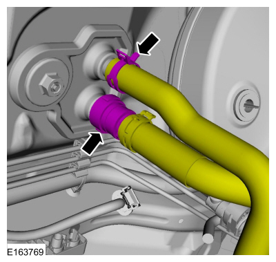
NOTE: Install the hoses as noted in removal.
Connect the heater hoses.
Use the General Equipment: Hose Clamp Remover/Installer
 |
-
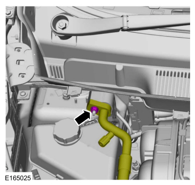
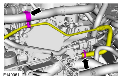
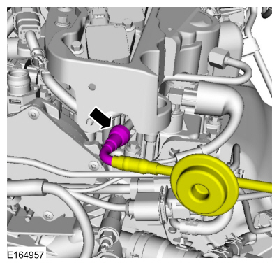
Connect the coolant tube and attach the retainer.
Use the General Equipment: Hose Clamp Remover/Installer
 |
-
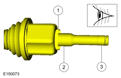
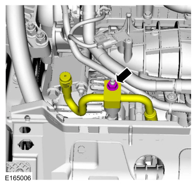
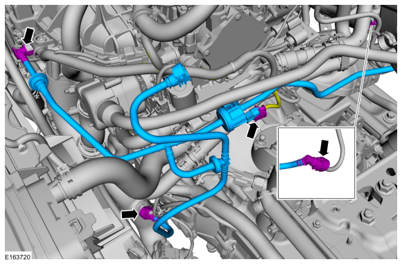
Install the fuel evaporative tube assembly. Connect the quick release couplings and the electrical connector.
 |
-
Early build vehicles, connect the fuel tube connection.
Refer to: Quick Release Coupling (310-00B Fuel System - General Information - 1.6L EcoBoost (132kW/180PS) – Sigma, General Procedures).
 |
-
Late build vehicles, connect the fuel tube connection.
Refer to: Spring Lock Couplings (310-00B Fuel System - General Information - 1.6L EcoBoost (132kW/180PS) – Sigma, General Procedures).
 |
-
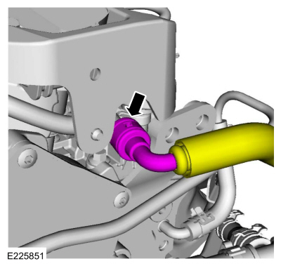
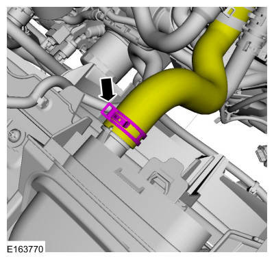
Install the coolant hose and the clamp.
Use the General Equipment: Hose Clamp Remover/Installer
 |
-
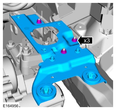
Install the bracket and the nuts.
Torque: 89 lb.in (10 Nm)
 |
-
Position the wiring harness and the install the retainers.
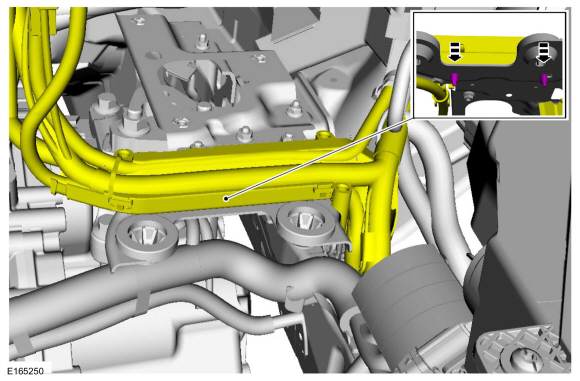 |
-
Position the wiring harness and the install the retainers.
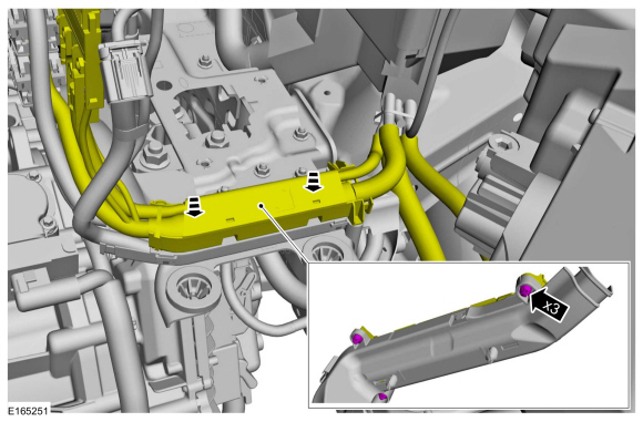 |
-
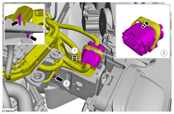
-
Position the wiring harness and attach the retainers.
-
Position the grounding wire and install the bolt.
Torque: 115 lb.in (13 Nm)
-
Connect the electrical connector.
-
Position the wiring harness and attach the retainers.
 |
-
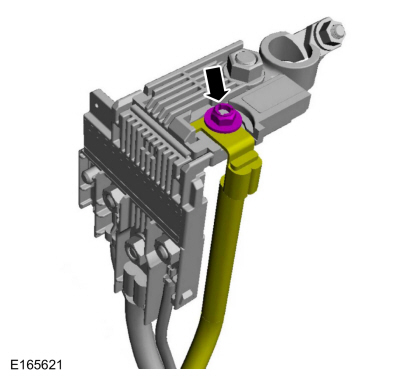
Install the wire and the nut.
Torque: 44 lb.in (5 Nm)
 |
-
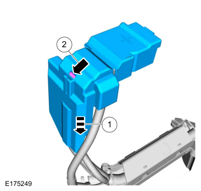
Install the battery terminal cover.
 |
-
Install the battery tray.
Refer to: Battery Tray - 1.6L EcoBoost (132kW/180PS) – Sigma (414-01 Battery, Mounting and Cables, Removal and Installation).
-
-
Install the air inlet pipe and the engine appearance cover stud and the nut.
Torque: 44 lb.in (5 Nm)
-
Tighten the clamp. Connect the crankcase ventilation tube coupling.
Torque: 44 lb.in (5 Nm)
-
Install the air inlet pipe and the engine appearance cover stud and the nut.
 |
-
Install the air cleaner outlet pipe and tighten the clamp. Connect the quick release coupling.
Torque: 44 lb.in (5 Nm)
 |
-
Install the air cleaner.
Refer to: Air Cleaner (303-12B Intake Air Distribution and Filtering - 1.6L EcoBoost (132kW/180PS) – Sigma, Removal and Installation).
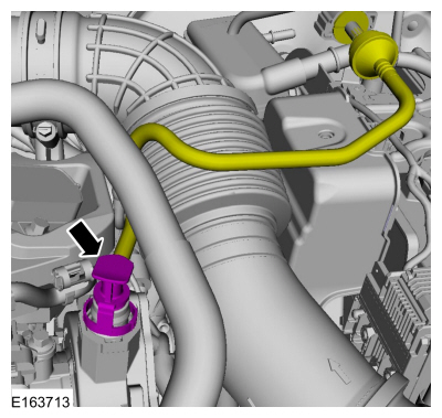
-
Connect the vacuum pump inlet tube coupling.
 |
-
Fill the engine with clean engine oil.
Material: Engine Oil - SAE 5W-20 - Synthetic Blend Motor Oil / XO-5W20-Q1SP (WSS-M2C945-B1)
-
Install the engine appearance cover.
 |
-
Fill the cooling system.
Refer to: Engine Cooling System Draining, Vacuum Filling and Bleeding (303-03B Engine Cooling - 1.6L EcoBoost (132kW/180PS) – Sigma, General Procedures).
-
Fill the A/C system.
Refer to: Air Conditioning (A/C) System Recovery, Evacuation and Charging (412-00 Climate Control System - General Information) .
-
Fill the transmission fluid.
Refer to: Transmission Draining and Filling (308-03B Manual Transmission - 6-Speed Manual Transmission – B6, General Procedures).
-
Bleed the clutch hydraulic system.
Refer to: Clutch System Bleeding (308-02 Clutch Controls - 5-Speed Manual Transmission – B5/IB5/6-Speed Manual Transmission – B6, General Procedures).
-
After completing the repairs, perform the Misfire Monitor Neutral Profile Correction procedure.
 Engine. Assembly
S..

Other information:
Ford Fiesta 2014 - 2019 Service Manual: Axle - 1.6L EcoBoost (132kW/180PS) – Sigma. Removal and Installation
Special Tool(s) / General Equipment Transmission Jack Vehicle/Axle Stands Removal NOTICE: Suspension fasteners are critical parts that affect performance of vital components and systems. Failure of these fasteners may result in major service expense. Use the same or equivalent parts if replacement is necessary. Do not use a replacement part of lesser quali..
Ford Fiesta 2014 - 2019 Service Manual: Manual Transmission. Diagnosis and Testing
Inspection and Verification NOTICE: If transmission noise is reported, check the fluid level first. Do not drive the vehicle if the fluid level is low or damage can occur. Verify the customer concern. Visually inspect for obvious signs of mechanical damage. Visual Inspection Chart Mechanical ..
Categories
- Manuals Home
- Ford Fiesta Service Manual (2014 - 2019)
- Valve Clearance Adjustment. General Procedures
- Engine System - General Information
- Front Subframe. Removal and Installation
- Engine Cooling - 1.6L EcoBoost (132kW/180PS) – Sigma
- Service Information
Rear Wheel Speed Sensor. Removal and Installation
Removal
NOTE: Removal steps in this procedure may contain installation details.
Remove the retainer and pull the rear splash shield outward. Disconnect the electrical connector and detach the wiring retainer.
Copyright © 2025 www.fofiesta7.com