Ford Fiesta: Front Drive Halfshafts / Front Halfshaft RH. Removal and Installation
Special Tool(s) / General Equipment
 |
204-161
(T97P-1175-A)
Installer, Halfshaft TKIT-1997-LM2 TKIT-1997-F/FM2 TKIT-1997-FLM2 |
 |
205-D070
(D93P-1175-B)
Remover, Front Wheel Hub |
Removal
NOTICE: Suspension fasteners are critical parts because they affect performance of vital components and systems and their failure may result in major service expense. New parts must be installed with the same part numbers or equivalent part, if replacement is necessary. Do not use a replacement part of lesser quality or substitute design. Torque values must be used as specified during reassembly to make sure of correct retention of these parts.
-
Remove the wheel and tire.
Refer to: Wheel and Tire (204-04A Wheels and Tires, Removal and Installation).
-
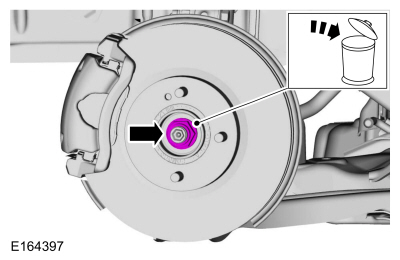
Remove and discard the wheel hub nut.
 |
-
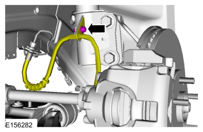
Remove the flexible brake hose bolt.
 |
-
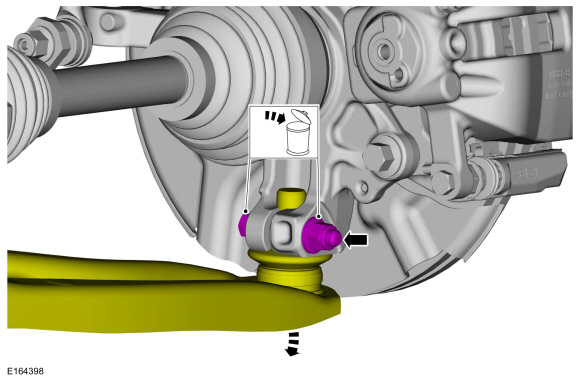
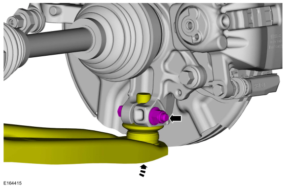
NOTICE: Do not use a prying device or separator fork between the ball joint and the wheel knuckle. Damage to the ball joint or ball joint seal may result. Only use the pry bar by inserting it into the lower arm body opening.
NOTICE: Use care when releasing the lower arm and wheel knuckle into the resting position or damage to the ball joint seal may result.
Remove and discard the lower ball joint nut and bolt. Disconnect the lower arm.
 |
-
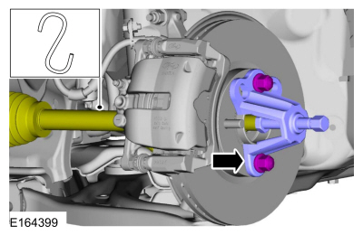
NOTICE: Do not bend the inner joint more than 18 degrees and the outer joint more than 45 degrees. Damage to the shaft will occur.
Using the special tool, press the RH halfshaft from the wheel bearing and hub. Support the RH halfshaft in a level position.
Use Special Service Tool: 205-D070 (D93P-1175-B) Remover, Front Wheel Hub.
 |
-
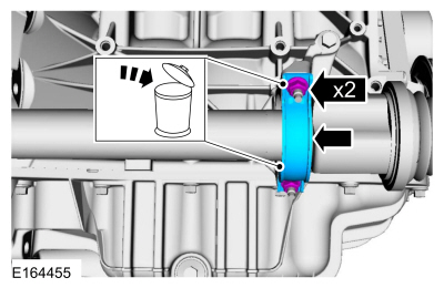
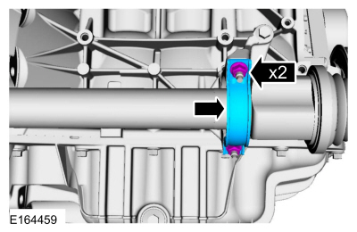
Remove and discard the halfshaft retaining strap and nuts.
 |
-
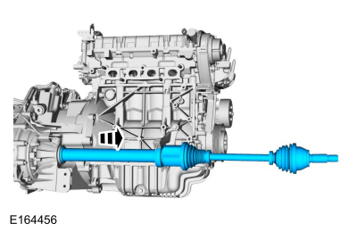
NOTE: Do not pull on the halfshaft or the CV joint will separate. Always pull on the intermediate shaft.
Remove the driveshaft.
 |
Installation
-
Install a new halfshaft seal.
Refer to: Halfshaft Seal RH (307-01 Automatic Transmission - 6-Speed PowerShift Transmission – DPS6/6DCT250, Removal and Installation).
Refer to: Halfshaft Seal RH (308-03A Manual Transmission - 5-Speed Manual Transmission – B5/IB5, Removal and Installation).
Refer to: Halfshaft Seal RH (308-03B Manual Transmission - 6-Speed Manual Transmission – B6, Removal and Installation).
-
NOTE: Do not fully install the shaft at this time.
Using seal protector, install the halfshaft splines through the seal protector and remove the seal protector.
 |
-
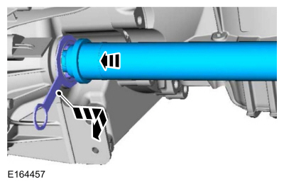
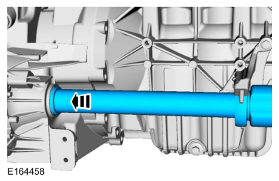
NOTE: Insert the intermediate shaft until the intermediate shaft bearing is centered in the concave groove of the intermediate shaft bearing bracket.
Insert the halfshaft until intermediate shaft bearing is seated in the intermediate shaft bearing bracket.
 |
-
Install the new intermediate shaft bearing strap and new intermediate shaft bearing strap nuts.
Torque:
Stage 1: Lower nut:: 44 lb.in (5 Nm)
Stage 2: Upper nut:: 18 lb.ft (25 Nm)
Stage 3: Lower nut:: 18 lb.ft (25 Nm)
 |
-
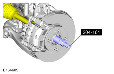
Using the special tool, install the LH halfshaft into the wheel bearing and hub.
Use Special Service Tool: 204-161 (T97P-1175-A) Installer, Halfshaft.
 |
-
Insert the lower ball joint into the wheel knuckle and install a new lower ball joint bolt and nut.
Torque: 38 lb.ft (52 Nm)
 |
-
Install the flexible brake hose bolt.
Torque: 19 lb.ft (26 Nm)
|
-
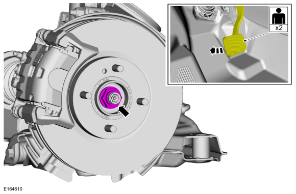
NOTICE: Do not tighten the front wheel hub nut with the vehicle on the ground. The nut must be tightened to specification before the vehicle is lowered onto the wheels. Wheel bearing damage will occur if the wheel bearing is loaded with the weight of the vehicle applied.
NOTICE: The wheel hub nut contains a one time locking chemical that is activated by the heat created when it is tightened. Install and tighten the new wheel hub nut to specification within 5 minutes of starting it on the threads. Always install a new wheel hub nut after loosening or when not tightened within the specified time or damage to the components can occur.
NOTE: Apply the brake to keep the halfshaft from rotating.
Using an assistant to apply brake pressure, install the new wheel hub nut.
Torque: 188 lb.ft (255 Nm)
 |
-
Check the transmission fluid level.
Refer to: Transmission Fluid Level Check (307-01 Automatic Transmission - 6-Speed PowerShift Transmission – DPS6/6DCT250, General Procedures).
Refer to: Transmission Fluid Level Check (308-03A Manual Transmission - 5-Speed Manual Transmission – B5/IB5, General Procedures).
Refer to: Transmission Fluid Level Check (308-03B Manual Transmission - 6-Speed Manual Transmission – B6, General Procedures).
-
Install the wheel and tire.
Refer to: Wheel and Tire (204-04A Wheels and Tires, Removal and Installation).
 Front Halfshaft LH. Removal and Installation
Special Tool(s) /
General Equipment
204-161
(T97P-1175-A)
Installer, HalfshaftTKIT-1997-LM2TKIT-1997-F/FM2TKIT-1997-FLM2
205-D070
(D93P-1175-B)
Remover, Front Wheel Hub
Removal
NOTICE:
Suspension fasteners are critical parts because they affect
performance of vital components and systems and their failure may result
in major service expense...
 Inner Constant Velocity (CV) Joint Boot. Removal and Installation
Special Tool(s) /
General Equipment
205-343
(T95P-3514-A)
Installer, Constant Velocity Joint Boot ClampTKIT-1995-FTKIT-1995-FM/FLMTKIT-1995-LM/M
Flat Headed Screw Driver
Puller
Bearing Separator
Vise
Materials
Name
Specification
Motorcraft® Constant Velocity Joint GreaseXG-5
WSS-M1C258-A1
Removal
..
Other information:
Ford Fiesta 2014 - 2019 Service Manual: Front Door Alignment. General Procedures
Inspection Check the body to the front door dimensions. Refer to: Body and Frame (501-26 Body Repairs - Vehicle Specific Information and Tolerance Checks, Description and Operation). Adjustment NOTE: Removal steps in this procedure may contain installation details. NOTE: LH side shown, RH side similar. All alignments Remove t..
Ford Fiesta 2014 - 2019 Service Manual: Liftgate. Removal and Installation
Removal NOTE: Removal steps in this procedure may contain installation details. Lower the headliner. Refer to: Headliner - 5-Door (501-05 Interior Trim and Ornamentation, Removal and Installation). Disconnect the electrical connector, detach the wiring harness retainers and route the wiring harness out of the liftgate. ..
Categories
- Manuals Home
- Ford Fiesta Service Manual (2014 - 2019)
- Maintenance Schedules - Gasoline Engines. Description and Operation
- Front Suspension
- Front Subframe. Removal and Installation
- Engine Cooling - 1.6L EcoBoost (132kW/180PS) – Sigma
- Manual Transmission - 6-Speed Manual Transmission – B6
Axle. Removal and Installation
Special Tool(s) / General Equipment
Flat Headed Screw Driver Transmission Jack Vehicle/Axle StandsRemoval
NOTICE: Suspension fasteners are critical parts that affect performance of vital components and systems. Failure of these fasteners may result in major service expense. Use the same or equivalent parts if replacement is necessary. Do not use a replacement part of lesser quality or substitute design. Tighten fasteners as specified.
Remove the floor console.Refer to: Floor Console (501-12 Instrum