Ford Fiesta: Front Drive Halfshafts / Front Halfshaft LH. Removal and Installation
Special Tool(s) / General Equipment
 |
204-161
(T97P-1175-A)
Installer, Halfshaft TKIT-1997-LM2 TKIT-1997-F/FM2 TKIT-1997-FLM2 |
 |
205-D070
(D93P-1175-B)
Remover, Front Wheel Hub |
Removal
NOTICE: Suspension fasteners are critical parts because they affect performance of vital components and systems and their failure may result in major service expense. New parts must be installed with the same part numbers or equivalent part, if replacement is necessary. Do not use a replacement part of lesser quality or substitute design. Torque values must be used as specified during reassembly to make sure of correct retention of these parts.
-
Remove the wheel and tire.
Refer to: Wheel and Tire (204-04A Wheels and Tires, Removal and Installation).
-
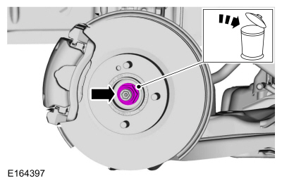
Remove and discard the wheel hub nut.
 |
-
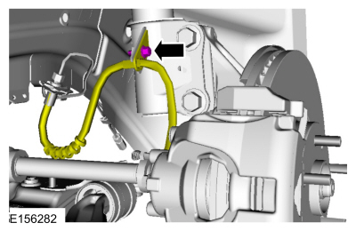
Remove the flexible brake hose bolt.
 |
-
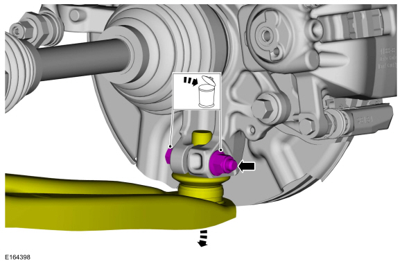
NOTICE: Do not use a prying device or separator fork between the ball joint and the wheel knuckle. Damage to the ball joint or ball joint seal may result. Only use the pry bar by inserting it into the lower arm body opening.
NOTICE: Use care when releasing the lower arm and wheel knuckle into the resting position or damage to the ball joint seal may result.
Remove and discard the lower ball joint nut and bolt. Disconnect the lower arm.
 |
-
NOTICE: Do not bend the inner joint more than 18 degrees and the outer joint more than 45 degrees. Damage to the shaft will occur.
Using the special tool, press the LH halfshaft from the wheel bearing and hub. Support the LH halfshaft in a level position.
Use Special Service Tool: 205-D070 (D93P-1175-B) Remover, Front Wheel Hub.
 |
-
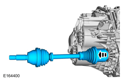
NOTE: Do not pull on the outer part of the halfshaft or the CV joint will separate. Always pull on the inner part of the halfshaft.
Remove and support the LH halfshaft from the transmission.
 |
Installation
-
Install a new halfshaft seal.
Refer to: Halfshaft Seal LH (307-01 Automatic Transmission - 6-Speed PowerShift Transmission – DPS6/6DCT250, Removal and Installation).
Refer to: Halfshaft Seal LH (308-03A Manual Transmission - 5-Speed Manual Transmission – B5/IB5, Removal and Installation).
Refer to: Halfshaft Seal LH (308-03B Manual Transmission - 6-Speed Manual Transmission – B6, Removal and Installation).
-
NOTE: Do not fully install the shaft at this time.
Using seal protector, install the halfshaft splines through the seal protector and remove the seal protector.
 |
-
NOTE: Insert shaft until circlip is fully seated. When checking if circlip is seated do not pull on CV joints or damage can result.
Insert the halfshaft until circlip seats properly.
 |
-
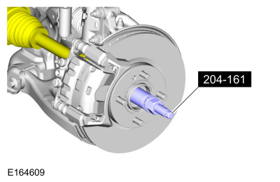
Using special tools, install the LH halfshaft into the wheel bearing and hub.
Use Special Service Tool: 204-161 (T97P-1175-A) Installer, Halfshaft.
 |
-
Insert the lower ball joint into the wheel knuckle and install a new lower ball joint bolt and nut.
Torque: 38 lb.ft (52 Nm)
 |
-
Install the flexible brake hose bolt.
Torque: 19 lb.ft (26 Nm)
 |
-
NOTICE: Do not tighten the front wheel hub nut with the vehicle on the ground. The nut must be tightened to specification before the vehicle is lowered onto the wheels. Wheel bearing damage will occur if the wheel bearing is loaded with the weight of the vehicle applied.
NOTICE: The wheel hub nut contains a one time locking chemical that is activated by the heat created when it is tightened. Install and tighten the new wheel hub nut to specification within 5 minutes of starting it on the threads. Always install a new wheel hub nut after loosening or when not tightened within the specified time or damage to the components can occur.
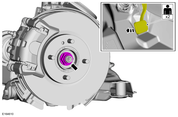
NOTE: Apply the brake to keep the halfshaft from rotating.
Using an assistant to apply brake pressure, install the new wheel hub nut.
Torque: 188 lb.ft (255 Nm)
 |
-
Check the transmission fluid level.
Refer to: Transmission Fluid Level Check (307-01 Automatic Transmission - 6-Speed PowerShift Transmission – DPS6/6DCT250, General Procedures).
Refer to: Transmission Fluid Level Check (308-03A Manual Transmission - 5-Speed Manual Transmission – B5/IB5, General Procedures).
Refer to: Transmission Fluid Level Check (308-03B Manual Transmission - 6-Speed Manual Transmission – B6, General Procedures).
-
Install the wheel and tire.
Refer to: Wheel and Tire (204-04A Wheels and Tires, Removal and Installation).
 Front Drive Halfshafts. Diagnosis and Testing
Inspection and Verification
Verify the customer concern.
Visually inspect for obvious signs of mechanical or electrical damage.
If an obvious cause for an observed or reported concern is
found, correct the cause (if possible) before proceeding to the next
step
If the cause is not visually evident, verify the symptom and refer to the Symptom Chart...
 Front Halfshaft RH. Removal and Installation
Special Tool(s) /
General Equipment
204-161
(T97P-1175-A)
Installer, HalfshaftTKIT-1997-LM2TKIT-1997-F/FM2TKIT-1997-FLM2
205-D070
(D93P-1175-B)
Remover, Front Wheel Hub
Removal
NOTICE:
Suspension fasteners are critical parts because they affect
performance of vital components and systems and their failure may result
in major service expense...
Other information:
Ford Fiesta 2014 - 2019 Service Manual: Pinpoint Test - DTC: W. Diagnosis and Testing
B1417:11 and B1417:93 Refer to Wiring Diagrams Cell 46 for schematic and connector information. The RCM monitors the RH front impact severity sensor circuits for the following faults: Open circuit Short to voltage Short to ground Faulted RH front impact severity sensor If a fault is detected, the RCM stores DTC B1417:11 or B1417:93 in m..
Ford Fiesta 2014 - 2019 Service Manual: Halfshaft Seal LH. Removal and Installation
Special Tool(s) / General Equipment 308-880Installer, Driveshaft Seal Removal Remove the wheel and tire. Refer to: Wheel and Tire (204-04A Wheels and Tires, Removal and Installation). Remove the bolt and position aside the LH brake hose. NOTICE: Do not use a prying device or separator fo..
Categories
- Manuals Home
- Ford Fiesta Service Manual (2014 - 2019)
- Front Subframe. Removal and Installation
- Fuel Rail. Removal and Installation
- Maintenance Schedules - Gasoline Engines. Description and Operation
- Engine Cooling - 1.6L EcoBoost (132kW/180PS) – Sigma
- Manual Transmission - 6-Speed Manual Transmission – B6
Ride Height Measurement. General Procedures
Special Tool(s) / General Equipment
Surface GaugeCheck
Ride Height Measurement - Front
NOTE: Make sure that the vehicle is positioned on a flat, level surface and the tires are inflated to the correct pressure. Vehicle should have a full tank of fuel.
Ride height = 2-3Measurement 2
Measurement 3
Use the General Equipment: Surface Gauge
