Ford Fiesta: Suspension System - General Information / Ride Height Measurement. General Procedures
Ford Fiesta 2014 - 2019 Service Manual / Suspension / Suspension System - General Information / Ride Height Measurement. General Procedures
Special Tool(s) / General Equipment
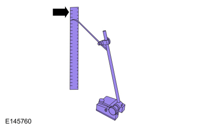
| Surface Gauge |
Check
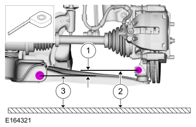
Ride Height Measurement - Front
NOTE: Make sure that the vehicle is positioned on a flat, level surface and the tires are inflated to the correct pressure. Vehicle should have a full tank of fuel.
-
-
Ride height = 2-3
-
Measurement 2
-
Measurement 3
Use the General Equipment: Surface Gauge
-
Ride height = 2-3
 |
-
With the surface gauge positioned on a flat, level
surface, record the measurement of the surface gauge position
(measurements 2 and 3).
Use the General Equipment: Surface Gauge
 |
-
Subtract measurement 2 from measurement 3 to obtain the front ride height.
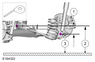
Ride Height Measurement - Rear
NOTE: Make sure that the vehicle is positioned on a flat, level surface and the tires are inflated to the correct pressure. Vehicle should have a full tank of fuel.
-
-
Ride height = 2-3
-
Measurement 2
-
Measurement 3
Use the General Equipment: Surface Gauge
-
Ride height = 2-3
 |
-
Measure the distance between the flat level surface and the forward lower arm inboard bolt (measurement 2).
-
Measure the distance between the flat level surface
and the center of the forward lower arm outboard bolt (measurement 3).
-
Subtract measurement 3 from measurement 2 to obtain the rear ride height.
 Suspension System. Diagnosis and Testing
Preliminary Inspection
Road test the vehicle.
If any suspension alignment or ride height concerns are present, GO to Symptom Chart — Suspension System...
 Front Toe Adjustment. General Procedures
Special Tool(s) /
General Equipment
Wheel Alignment System
Adjustment
NOTE:
Make sure that the vehicle is standing on a level surface...
Other information:
Ford Fiesta 2014 - 2019 Service Manual: Front Door Alignment. General Procedures
Inspection Check the body to the front door dimensions. Refer to: Body and Frame (501-26 Body Repairs - Vehicle Specific Information and Tolerance Checks, Description and Operation). Adjustment NOTE: Removal steps in this procedure may contain installation details...
Ford Fiesta 2014 - 2019 Service Manual: Rear Door Speaker. Removal and Installation
Removal NOTE: Removal steps in this procedure may contain installation details. Remove the rear door trim panel. Refer to: Rear Door Trim Panel (501-05 Interior Trim and Ornamentation, Removal and Installation). Remove the bolts and the rear door speaker...
Categories
- Manuals Home
- Ford Fiesta Service Manual (2014 - 2019)
- Camshafts. Removal and Installation
- Clutch - 6-Speed Manual Transmission – B6
- Engine
- Front Subframe. Removal and Installation
- Engine Component View. Description and Operation
Parking Brake Control. Removal and Installation
Removal
NOTE: Removal steps in this procedure may contain installation details.
Remove the floor console.Refer to: Floor Console (501-12 Instrument Panel and Console, Removal and Installation).
Remove the driver seat.
Refer to: Front Seat (501-10 Seating, Removal and Installation).
Remove the parking brake cable adjustment lock nut.
 Loosen the parking brake cable adjustment nut.
Copyright © 2026 www.fofiesta7.com