Ford Fiesta: Exterior Lighting / Autolamps. Diagnosis and Testing
Diagnostics in this manual assume a certain skill level and knowledge of Ford-specific diagnostic practices.
REFER to: Diagnostic Methods (100-00 General Information, Description and Operation).
DTC Chart: BCM
BCM DTC Chart
| DTC | Description | Action |
|---|---|---|
| B1A85:21 | Ambient Light Sensor: Signal Amplitude < Minimum | GO to Pinpoint Test B |
| B1A85:22 | Ambient Light Sensor: Signal Amplitude > Maximum | GO to Pinpoint Test B |
Symptom Chart(s)
Diagnostics in this manual assume a certain skill level and knowledge of Ford-specific diagnostic practices.
REFER to: Diagnostic Methods (100-00 General Information, Description and Operation).
Symptom Chart: Autolamps
Symptom Chart
| Condition | Possible Sources | Actions |
|---|---|---|
| A module does not respond to the diagnostic scan tool |
|
REFER to: Communications Network (418-00 Module Communications Network, Diagnosis and Testing). |
| The autolamps are inoperative | Refer to the Pinpoint Test | GO to Pinpoint Test A |
| The autolamps are on continuously | Refer to the Pinpoint Test | GO to Pinpoint Test B |
Pinpoint Tests
The Autolamps Are Inoperative
Refer to Wiring Diagrams Cell 71 for schematic and connector information.
Normal Operation and Fault Conditions
REFER to: Exterior Lighting - System Operation and Component Description (417-01 Exterior Lighting, Description and Operation).
Possible Sources
- Light sensor
- Headlamp switch
- BCM
PINPOINT TEST A: THE AUTOLAMPS ARE INOPERATIVE
| A1 CHECK FOR VOLTAGE TO THE LIGHT SENSOR | ||||||||||||||||
Is the voltage approximately 5 volts?
|
||||||||||||||||
| A2 CHECK FOR CORRECT BCM (BODY CONTROL MODULE) OPERATION | ||||||||||||||||
Is the concern still present?
|

The Autolamps Are On Continuously
Refer to Wiring Diagrams Cell 71 for schematic and connector information.
Normal Operation and Fault Conditions
REFER to: Exterior Lighting - System Operation and Component Description (417-01 Exterior Lighting, Description and Operation).
DTC Fault Trigger Conditions
| DTC | Description | Fault Trigger Conditions |
|---|---|---|
| B1A85:21 | Ambient Light Sensor: Signal Amplitude < Minimum | A continuous memory DTC that sets when the BCM detects a short to ground from the light sensor input circuit. |
| B1A85:22 | Ambient Light Sensor: Signal Amplitude > Maximum | A continuous memory DTC that sets when the BCM detects an open or short to voltage from the light sensor input circuit. |
Possible Sources
- Wiring, terminals or connectors
- Light sensor
- Headlamp switch
- BCM
Visual Inspection and Diagnostic Pre-checks
- Inspect the headlamp switch for damage.
- Inspect the light sensor for damage.
PINPOINT TEST B: THE AUTOLAMPS ARE ON CONTINUOUSLY
| B1 CHECK FOR BCM (BODY CONTROL MODULE) DIAGNOSTIC TROUBLE CODE (DTCS) | ||||||||||||||||
Is DTC B1A85:21 or B1A85:22 present?
|
||||||||||||||||
| B2 CHECK FOR VOLTAGE TO THE LIGHT SENSOR (NO DTC (DIAGNOSTIC TROUBLE CODE) ) | ||||||||||||||||
Is the voltage approximately 5 volts?
|
||||||||||||||||
| B3 CHECK FOR VOLTAGE TO THE LIGHT SENSOR (DTC (DIAGNOSTIC TROUBLE CODE) B1A85:21) | ||||||||||||||||
Is the voltage approximately 5 volts?
|
||||||||||||||||
| B4 CHECK THE LIGHT SENSOR INPUT CIRCUIT FOR A SHORT TO GROUND | ||||||||||||||||
Is the resistance greater than 10,000 ohms?
|
||||||||||||||||
| B5 CHECK FOR VOLTAGE TO THE LIGHT SENSOR (DTC (DIAGNOSTIC TROUBLE CODE) B1A85:22) | ||||||||||||||||
Is the voltage approximately 5 volts?
|
||||||||||||||||
| B6 CHECK THE LIGHT SENSOR | ||||||||||||||||
Is the voltage approximately 5 volts?
|
||||||||||||||||
| B7 CHECK THE LIGHT SENSOR GROUND CIRCUIT FOR AN OPEN | ||||||||||||||||
Is the resistance less than 3 ohms?
|
||||||||||||||||
| B8 CHECK THE LIGHT SENSOR INPUT CIRCUIT FOR A SHORT TO VOLTAGE | ||||||||||||||||
Is any voltage present?
|
||||||||||||||||
| B9 CHECK THE LIGHT SENSOR INPUT CIRCUIT FOR AN OPEN | ||||||||||||||||
Is the resistance less than 3 ohms?
|
||||||||||||||||
| B10 CHECK FOR CORRECT BCM (BODY CONTROL MODULE) OPERATION | ||||||||||||||||
Is the concern still present?
|

 Turn Signal and Hazard Lamps. Diagnosis and Testing
Diagnostics in this manual assume a certain skill level and knowledge of Ford-specific diagnostic practices. REFER to: Diagnostic Methods (100-00 General Information, Description and Operation)...
 Daytime Running Lamps (DRL). Diagnosis and Testing
Symptom Chart(s)
Diagnostics in this manual assume a certain skill level and knowledge of Ford-specific diagnostic practices.REFER to: Diagnostic Methods (100-00 General Information, Description and Operation)...
Other information:
Ford Fiesta 2014 - 2019 Service Manual: Rear Door Window Control Switch. Removal and Installation
Removal NOTE: LH side shown, RH side similar. Remove the rear door window control switch. Remove the rear door window control switch from the door trim panel. Disconnect the rear door window control switch electrical connector...
Ford Fiesta 2014 - 2019 Service Manual: Rear Door Alignment. General Procedures
Inspection Check the body to the rear door dimensions. Refer to: Body and Frame (501-26 Body Repairs - Vehicle Specific Information and Tolerance Checks, Description and Operation). Adjustment NOTE: LH side shown, RH side similar...
Categories
- Manuals Home
- Ford Fiesta Service Manual (2014 - 2019)
- Engine
- Front Strut and Spring Assembly. Removal and Installation
- Maintenance Schedules - Gasoline Engines. Description and Operation
- Manual Transmission - 6-Speed Manual Transmission – B6
- Maintenance Schedules
Brake Backing Plate. Removal and Installation
Removal
NOTE: Removal steps in this procedure may contain installation details.
Remove the brake shoes.Refer to: Brake Shoes (206-02 Drum Brake, Removal and Installation).
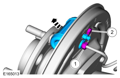
Disconnect the brake tube fitting.
Torque: 159 lb.in (18 Nm) Remove the bolt and wheel cylinder.
Torque: 106 lb.in (12 Nm)
 Disconnect the brake shoe lever fitting and re