Ford Fiesta: Rear Suspension / Axle. Removal and Installation
Special Tool(s) /
General Equipment
| Flat Headed Screw Driver |
| Transmission Jack |
| Vehicle/Axle Stands |
Removal
NOTICE:
Suspension fasteners are critical parts that affect
performance of vital components and systems. Failure of these fasteners
may result in major service expense. Use the same or equivalent parts if
replacement is necessary. Do not use a replacement part of lesser
quality or substitute design. Tighten fasteners as specified.
-
Remove the floor console.
Refer to: Floor Console (501-12 Instrument Panel and Console, Removal and Installation).
-
Remove the parking brake adjustment nut retaining clip.
-
Loosen the parking brake adjustment nut.
Loosen:
:
5 turn(s)
-
Remove the wheel and tire.
Refer to: Wheel and Tire (204-04A Wheels and Tires, Removal and Installation).
-
Remove the spring.
Refer to: Spring (204-02 Rear Suspension, Removal and Installation).
-
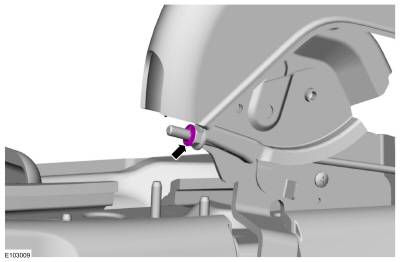
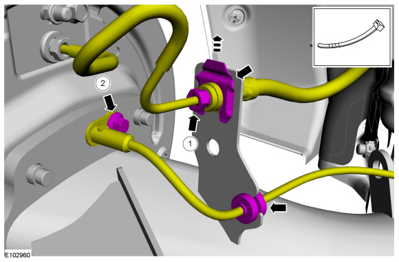
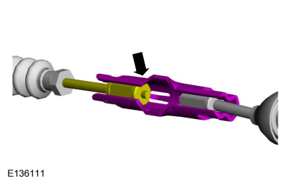
On both sides.
Using a screwdriver, pry up on the parking brake cable coupler locking tab.
Use the General Equipment: Flat Headed Screw Driver
-
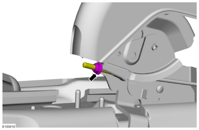
On both sides.
Separate the rear parking brake cable.
-
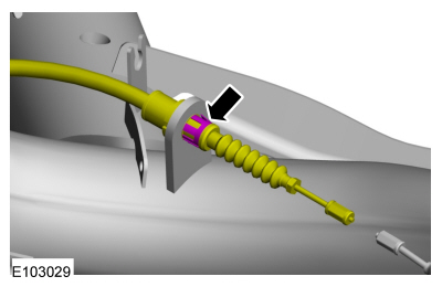
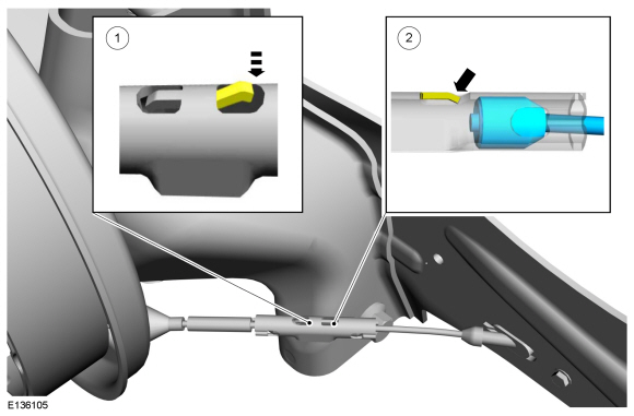
On both sides.
Compress the clip and pull the parking brake cable through the mounting bracket.
-
NOTE:
Cap the brake tube connections to prevent fluid loss.
On both sides.
-
Disconnect the rear brake tube fitting from the rear brake hose and remove the clip.
-
Remove the wheel speed sensor bolt and remove the wheel speed sensor.
-
Remove the wheel bearing and wheel hub.
Refer to: Wheel Bearing and Wheel Hub (204-02 Rear Suspension, Removal and Installation).
-
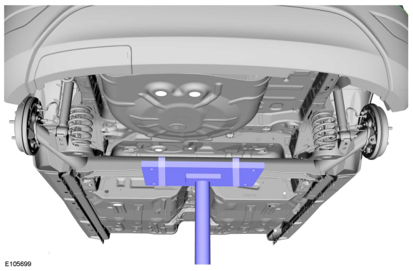
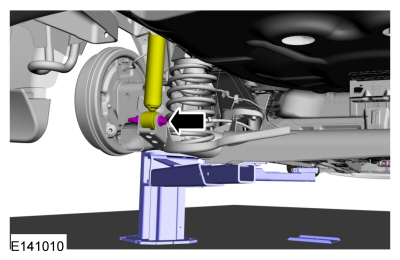
Support the rear axle assembly.
Use the General Equipment: Transmission Jack
-
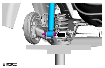
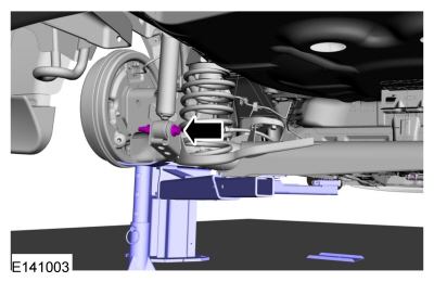
On both sides.
Remove the shock absorber lower bolt and nut.
-
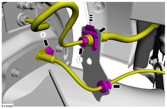
-
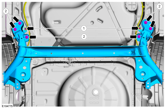
Remove the parking brake cable bracket nuts.
-
Remove the bracket-to-frame bolts and remove the axle assembly
Installation
-
Position the axle assembly.
-
Install the parking brake cable bracket nuts.
Torque:
18 lb.ft (25 Nm)
-
Install the axle assembly bracket-to-frame bolts.
Torque:
92 lb.ft (125 Nm)
-
NOTE:
Only tighten the bolts finger tight at this stage.
On both sides.
Install the shock absorber lower bolt and nut.
-
Install the wheel bearing and wheel hub.
Refer to: Wheel Bearing and Wheel Hub (204-02 Rear Suspension, Removal and Installation).
-
On both sides.
-
Install the clip and connect the rear brake tube fitting.
Torque:
150 lb.in (17 Nm)
-
Install the wheel speed sensor and install the wheel speed sensor bolt.
Torque:
89 lb.in (10 Nm)
-
On both sides.
Position the parking brake cable into the mounting bracket and engage the locking clip.
-
On both sides.
Attach the rear parking brake cable.
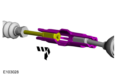
-
-
Using a screwdriver, press the parking brake coupler locking tab downwards.
-
Insert the parking brake cable and position the tab.
-
Install the spring.
Refer to: Spring (204-02 Rear Suspension, Removal and Installation).
-
On both sides.
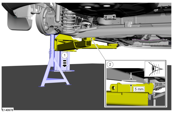
Position the axle stand supporting the beam axle. Lower
the hoist, maintaining 5mm gap between vehicle and the hoist.
Use the General Equipment: Vehicle/Axle Stands
-
On both sides.
Tighten the shock absorber lower bolt and nut.
Torque:
85 lb.ft (115 Nm)
-
Install the wheel and tire.
Refer to: Wheel and Tire (204-04A Wheels and Tires, Removal and Installation).
-
Bleed the brake system.
Refer to: Brake System Pressure Bleeding (206-00 Brake System - General Information, General Procedures).
-
NOTE:
The brake shoes and parking brake cables must both
be adjusted to assure correct rear drum brake and parking brake system
operation.
Adjust the parking brake cable.
Refer to: Parking Brake Cable Adjustment (206-05 Parking Brake and Actuation, General Procedures).
-
Install the floor console.
Refer to: Floor Console (501-12 Instrument Panel and Console, Removal and Installation).
Special Tool(s) /
General Equipment
Transmission Jack
Vehicle/Axle Stands
Removal
With the vehicle in NEUTRAL, position it on a hoist...
Special Tool(s) /
General Equipment
Transmission Jack
Vehicle/Axle Stands
Removal
NOTICE:
Suspension fasteners are critical parts that affect
performance of vital components and systems...
Other information:
U2300:55, U2300:64
Refer to Wiring Diagrams Cell 46 for schematic and connector information.
NOTE:
DTC U2300:55 is set in every new RCM installed until configuration data
is successfully received from the IPC . DO NOT install any new
components for this DTC unless directed to do so in the pinpoint test...
Special Tool(s) /
General Equipment
Spatula
Adhesive Tape
Removal
If equipped.
Remove the pushpin type retainer and the rocker panel moulding end cap.
Clean the area and remove any remaining residue...

 Rear Shock Absorber. Removal and Installation
 Axle - 1.6L EcoBoost (132kW/180PS) – Sigma. Removal and Installation