Ford Fiesta: Rear Suspension / Spring. Removal and Installation
Ford Fiesta 2014 - 2019 Service Manual / Suspension / Rear Suspension / Spring. Removal and Installation
Special Tool(s) / General Equipment
| Spring Compressor |
Removal
NOTE: Removal steps in this procedure may contain installation details.
-
With the vehicle in NEUTRAL, position it on a hoist.
Refer to: Jacking and Lifting - Overview (100-02 Jacking and Lifting, Description and Operation).
-
 WARNING:
The coil spring is under extreme load. Care must be
taken at all times when removing or installing a loaded spring. Failure
to follow this instruction may result in serious personal injury.
WARNING:
The coil spring is under extreme load. Care must be
taken at all times when removing or installing a loaded spring. Failure
to follow this instruction may result in serious personal injury.
-
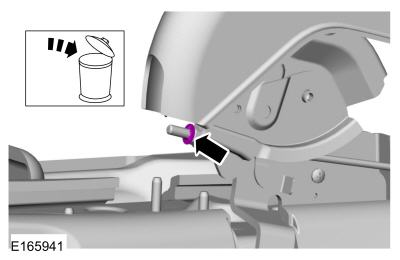
On both sides.
Compress the coil spring using the spring compressor.
Use the General Equipment: Spring Compressor
-
On both sides.
Remove the coil spring with the spring compressor.
-
On both sides.
 |
Installation
-
NOTE: Make sure the upper spring seat is installed, and the spring ends butt correctly against the upper and lower spring seats.
To install, reverse the removal procedure.
 Axle - 1.6L EcoBoost (132kW/180PS) – Sigma. Removal and Installation
Special Tool(s) /
General Equipment
Transmission Jack
Vehicle/Axle Stands
Removal
NOTICE:
Suspension fasteners are critical parts that affect
performance of vital components and systems...
 Trailing Arm Bushing. Removal and Installation
Special Tool(s) /
General Equipment
205-199
(T83T-3132-A1)
Installer, Spindle/Axle ShaftT83-4000-ATKIT-1983-FTKIT-1983-FLMTKIT-1983-FX
205-353
(T95T-3132-C)
Installer, Front Wheel Spindle Oil SealTKIT-1995-FTKIT-1995-FM/FLM
308-062
(T77J-7025-M)
Installer, Input Shaft Bearing
Transmission Jack
Vehicle/Axle Stands
Removal
..
Other information:
Ford Fiesta 2014 - 2019 Service Manual: Stoplamp Switch. Removal and Installation
Removal NOTE: Removal steps in this procedure may contain installation details. NOTICE: Do not press, pull or otherwise move the brake pedal while installing the stoplamp switch and cruise control deactivation switch. Install these switches with the booster push rod attached to the brake pedal and with the brake pedal in the at-rest position. Installing these switc..
Ford Fiesta 2014 - 2019 Service Manual: Valve Clearance Adjustment. General Procedures
Special Tool(s) / General Equipment Feeler Gauge Materials Name Specification Engine Oil - SAE 5W-20 - Synthetic Blend Motor OilXO-5W20-Q1SP WSS-M2C945-B1 Flange SealantCU7Z-19B508-A WSS-M2G348-A11 Check Refer to: Valve Cover (303-01B Engine - 1.6L EcoBoost (132kW/180PS) – Sigma, Removal and Installation). ..
Categories
- Manuals Home
- Ford Fiesta Service Manual (2014 - 2019)
- Engine - 1.6L EcoBoost (132kW/180PS) – Sigma
- Camshafts. Removal and Installation
- Manual Transmission, Clutch, Transfer Case and Power Transfer Unit
- Service Information
- Fuel Rail. Removal and Installation
Parking Brake Control. Removal and Installation
Removal
NOTE: Removal steps in this procedure may contain installation details.
Remove the floor console.Refer to: Floor Console (501-12 Instrument Panel and Console, Removal and Installation).
Remove the driver seat.
Refer to: Front Seat (501-10 Seating, Removal and Installation).
Remove the parking brake cable adjustment lock nut.
 Loosen the parking brake cable adjustment nut.
Copyright © 2025 www.fofiesta7.com