Ford Fiesta: Rear Suspension / Trailing Arm Bushing. Removal and Installation
Ford Fiesta 2014 - 2019 Service Manual / Suspension / Rear Suspension / Trailing Arm Bushing. Removal and Installation
Special Tool(s) / General Equipment
 |
205-199
(T83T-3132-A1)
Installer, Spindle/Axle Shaft T83-4000-A TKIT-1983-F TKIT-1983-FLM TKIT-1983-FX |
 |
205-353
(T95T-3132-C)
Installer, Front Wheel Spindle Oil Seal TKIT-1995-F TKIT-1995-FM/FLM |
 |
308-062
(T77J-7025-M)
Installer, Input Shaft Bearing |
| Transmission Jack | |
| Vehicle/Axle Stands | |
Removal
NOTICE: Suspension fasteners are critical parts that affect performance of vital components and systems. Failure of these fasteners may result in major service expense. Use the same or equivalent parts if replacement is necessary. Do not use a replacement part of lesser quality or substitute design. Tighten fasteners as specified.
-
Remove the wheel and tire.
Refer to: Wheel and Tire (204-04A Wheels and Tires, Removal and Installation).
-
Support the rear axle assembly.
Use the General Equipment: Transmission Jack
 |
-
-
Remove the parking brake cable bracket nuts.
-
Remove the bracket-to-frame bolts and remove the axle assembly
-
Remove the parking brake cable bracket nuts.
 |
-
On both sides.
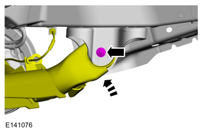
Lower rear axle assembly and remove and discard the trailing arm nut and bolt.
 |
-
Using the special tools, remove the trailing arm bushing.
Use Special Service Tool: 205-199 (T83T-3132-A1) Installer, Spindle/Axle Shaft. , 205-353 (T95T-3132-C) Installer, Front Wheel Spindle Oil Seal.
 |
Installation
-
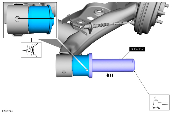
Using the special tool, install the trailing arm bushing.
Use Special Service Tool: 308-062 (T77J-7025-M) Installer, Input Shaft Bearing.
 |
-
NOTE: Only tighten the bolts finger tight at this stage.
On both sides.
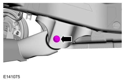
Position the rear axle assembly and install the new trailing arm nut and bolt.
 |
-
Position the rear axle assembly.
-
Install the parking brake cable bracket nuts.
Torque: 18 lb.ft (25 Nm)
-
Install the axle assembly bracket-to-frame bolts.
Torque: 92 lb.ft (125 Nm)
-
Install the parking brake cable bracket nuts.
 |
-
On both sides.
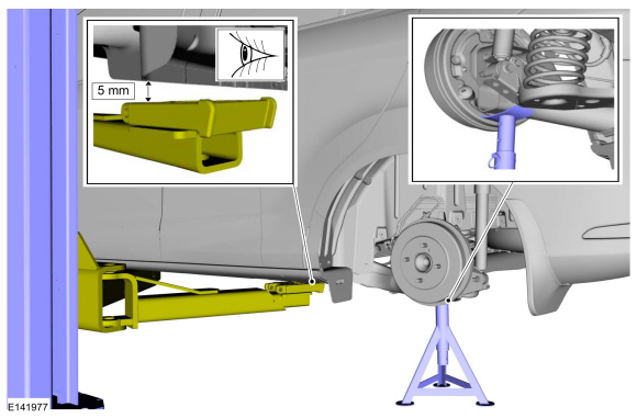
Position the axle stand supporting the beam axle. Lower the hoist, maintaining 5mm gap between vehicle and the hoist.
Use the General Equipment: Vehicle/Axle Stands
 |
-
On both sides.
Tighten the new trailing arm nut and bolt.
Torque:
Stage 1: 59 lb.ft (80 Nm)
Stage 2: 120°
 |
-
Install the wheel and tire.
Refer to: Wheel and Tire (204-04A Wheels and Tires, Removal and Installation).
 Spring. Removal and Installation
Special Tool(s) /
General Equipment
Spring Compressor
Removal
NOTE:
Removal steps in this procedure may contain installation details...
 Wheel Bearing and Wheel Hub. Removal and Installation
Removal
NOTICE:
Suspension fasteners are critical parts that affect
performance of vital components and systems. Failure of these fasteners
may result in major service expense...
Other information:
Ford Fiesta 2014 - 2019 Service Manual: Paintwork Defects and Damage. General Procedures
Materials Name Specification Motorcraft® Acid NeutralizerZC-1-A - Motorcraft® Alkaline NeutralizerZC-2-A - Repair NOTE: Refinishing - Environmental Damage WARNING: Before beginning any service procedure in this manual, refer to health and safety warnings in section 100-00 General Information...
Ford Fiesta 2014 - 2019 Service Manual: Air Conditioning (A/C) Compressor Inlet Line - 1.6L EcoBoost (132kW/180PS) – Sigma. Removal and Installation
Removal NOTE: Removal steps in this procedure may contain installation details. Recover the refrigerant. Refer to: Air Conditioning (A/C) System Recovery, Evacuation and Charging (412-00 Climate Control System - General Information) ...
Categories
- Manuals Home
- Ford Fiesta Service Manual (2014 - 2019)
- Maintenance Schedules
- Engine. Assembly
- Front Suspension
- Fuel Rail. Removal and Installation
- Engine Cooling - 1.6L EcoBoost (132kW/180PS) – Sigma
Brake Master Cylinder. Removal and Installation
Removal
NOTICE: If the fluid is spilled on the paintwork, the affected area must be immediately washed down with cold water.
NOTE: Removal steps in this procedure may contain installation details.
All vehicles
Remove the battery tray.Refer to: Battery Tray - 1.6L Duratec-16V Ti-VCT (88kW/120PS) – Sigma (414-01 Battery, Mounting and Cables, Removal and Installation).
Refer to: Battery Tray - 1.6L EcoBoost (132kW/180PS) – Sigma (414-01 Battery, Mounting and Cables, Removal and Installation).
Disconnect the vacuum tube from the brake booster and detach the routing clip.
Copyright © 2025 www.fofiesta7.com
