Ford Fiesta: Rear Suspension / Wheel Bearing and Wheel Hub. Removal and Installation
Removal
NOTICE: Suspension fasteners are critical parts that affect performance of vital components and systems. Failure of these fasteners may result in major service expense. Use the same or equivalent parts if replacement is necessary. Do not use a replacement part of lesser quality or substitute design. Tighten fasteners as specified.
-
Remove the brake drum.
Refer to: Brake Drum (206-02 Drum Brake, Removal and Installation).
-
Remove the wheel speed sensor bolt and position aside the wheel speed sensor.
 |
-
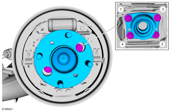
NOTE: Wheel hub is removed for clarity.
-
Remove and discard the wheel bearing and wheel hub assembly bolts.
-
Remove the wheel bearing and wheel hub assembly.
-
Support the brake backing plate assembly.
-
Remove and discard the wheel bearing and wheel hub assembly bolts.
 |
Installation
-
Position the brake backing plate assembly.
-
Install the wheel bearing and wheel hub assembly.
-
Install the new wheel bearing and wheel hub assembly bolts.
Torque: 48 lb.ft (65 Nm)
-
Install the wheel bearing and wheel hub assembly.
 |
-
-
Tighten the wheel bearing and wheel hub assembly bolt.
Torque:
Stage 1: Loosen:: 90°
Stage 2: 48 lb.ft (65 Nm)
-
Tighten the wheel bearing and wheel hub assembly bolt.
Torque:
Stage 1: Loosen: : 90°
Stage 2: 48 lb.ft (65 Nm)
-
Tighten the wheel bearing and wheel hub assembly bolt.
Torque:
Stage 1: Loosen:: 90°
Stage 2: 48 lb.ft (65 Nm)
-
Tighten the wheel bearing and wheel hub assembly bolt.
Torque:
Stage 1: Loosen: : 90°
Stage 2: 48 lb.ft (65 Nm)
-
Tighten the wheel bearing and wheel hub assembly bolt.
 |
-
Position the wheel speed sensor and install the wheel speed sensor bolt.
Torque: 80 lb.in (9 Nm)
|
-
Install the brake drum.
Refer to: Brake Drum (206-02 Drum Brake, Removal and Installation).

 Rear Wheel Bearing - 1.6L EcoBoost (132kW/180PS) – Sigma. Removal and Installation
Special Tool(s) /
General Equipment
204-023
(T73T-1217-A)
Installer, Wheel Hub Bearing Cup
204-180
(T93P-5493-A)
Remover/Installer, BushingTKIT-1993-FLMTKIT-1993-LMTKIT-1993-FM
205-140
(T80T-4000-F)
Installer, Drive Pinion Bearing Cup
205-153
(T80T-4000-W)
Handle
205-510Receiving Cup, Axle BushingTKIT-2002N-F/FMTKIT-2002N-FLMT..
Other information:
Ford Fiesta 2014 - 2019 Service Manual: Radiator Lower Hose. Removal and Installation
Special Tool(s) / General Equipment Hose Clamp Remover/Installer Removal Drain the cooling system. Refer to: Engine Cooling System Draining, Vacuum Filling and Bleeding (303-03B Engine Cooling - 1.6L EcoBoost (132kW/180PS) – Sigma, General Procedures). Remove the generator. Refer to: Generator - 1.6L EcoBoost (132kW/180PS) – Sigma (414-0..
Ford Fiesta 2014 - 2019 Service Manual: Horn. Removal and Installation
Removal NOTE: The removal steps in this procedure may include installation details. Remove the RH headlamp assembly. Refer to: Headlamp Assembly (417-01 Exterior Lighting, Removal and Installation). Disconnect the electrical connector, remove the bolt and the horn. Torque: 17 lb.ft (23 Nm) Installation ..
Categories
- Manuals Home
- Ford Fiesta Service Manual (2014 - 2019)
- Manual Transmission - 6-Speed Manual Transmission – B6
- Engine
- Service Information
- Transmission Fluid Level Check. General Procedures
- Front Strut and Spring Assembly. Removal and Installation
Component Bleeding. General Procedures
Special Tool(s) / General Equipment
Master Cylinder Bleeding SetBleeding
NOTICE: If the fluid is spilled on the paintwork, the affected area must be immediately washed down with cold water.
Master Cylinder
NOTE: When a new brake master cylinder has been installed, it should be primed to prevent air from entering the system.
NOTE: Make sure the area around the master cylinder cap is clean and free of foreign material.
Remove the brake fluid reservoir cap.