Ford Fiesta: Engine - 1.6L EcoBoost (132kW/180PS) – Sigma / Intake Manifold. Removal and Installation
Ford Fiesta 2014 - 2019 Service Manual / Engine / Engine - 1.6L EcoBoost (132kW/180PS) – Sigma / Intake Manifold. Removal and Installation
Special Tool(s) / General Equipment
| Hose Clamp Remover/Installer |
Removal
-
With the vehicle in NEUTRAL, position it on a hoist.
Refer to: Jacking and Lifting - Overview (100-02 Jacking and Lifting, Description and Operation).
-
Disconnect the battery ground.
Refer to: Battery Disconnect and Connect (414-01 Battery, Mounting and Cables, General Procedures).
-
Remove the generator.
Refer to: Generator - 1.6L EcoBoost (132kW/180PS) – Sigma (414-02 Generator and Regulator, Removal and Installation).
-
-
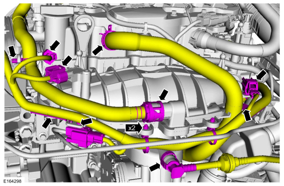
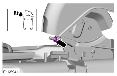
Disconnect the PCV hose from the valve cover.
Use the General Equipment: Hose Clamp Remover/Installer
-
Disconnect the EVAP canister purge valve quick release connector.
-
Detach the wiring harness retainers and disconnect the electrical connectors.
-
Disconnect the PCV hose from the valve cover.
 |
-
-
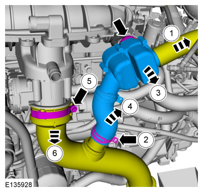
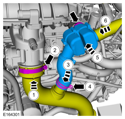
Disconnect the resonator assembly hose. Loosen the clamps and remove the resonator assembly.
Use the General Equipment: Hose Clamp Remover/Installer
-
Loosen the clamps and position aside the CAC hose.
-
Disconnect the resonator assembly hose. Loosen the clamps and remove the resonator assembly.
 |
-
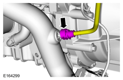
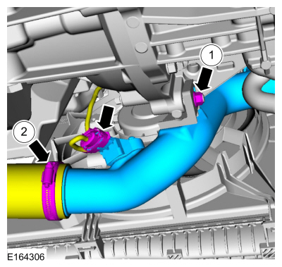
Disconnect the EVAP tube from the CAC outlet tube.
 |
-
-
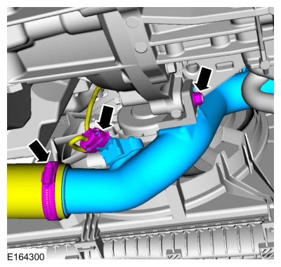
Disconnect the electrical connector.
-
Loosen the clamp, remove the nut and the CAC outlet tube.
-
Disconnect the electrical connector.
 |
-
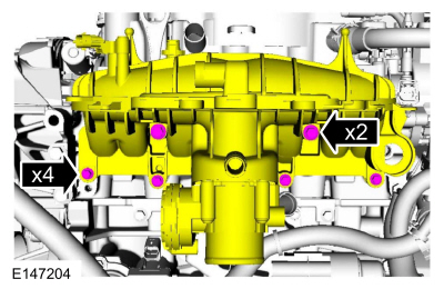
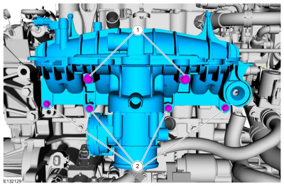
NOTE: Note the different lengths of the bolts for installation.
Remove the intake manifold bolts.
 |
-
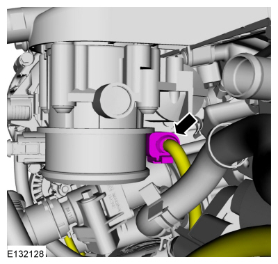
Disconnect the throttle body electrical connector.
 |
-
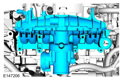
Remove the intake manifold.
 |
Installation
NOTICE: If the engine is repaired or replaced because of upper engine failure, typically including valve or piston damage, check the intake manifold for metal debris. If metal debris is found, install a new intake manifold. Failure to follow these instructions can result in engine damage.
-
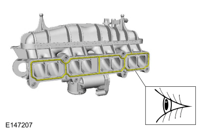
NOTE: Visually inspect the intake manifold gaskets for nicks, cuts and abrasions. If these conditions are not present, the gaskets may be re-used.
Inspect the intake manifold gaskets for nicks.
 |
-
Connect the throttle body electrical connector.
|
-
NOTE: There are different length of bolts noted in removal.
-
Install the intake manifold and the bolts.
Torque: 150 lb.in (17 Nm)
-
Install the intake manifold bolts.
Torque: 89 lb.in (10 Nm)
-
Install the intake manifold and the bolts.
 |
-
-
Install the CAC outlet tube and the nut.
Torque: 133 lb.in (15 Nm)
-
Tighten the hose clamp and connect the electrical connector.
Torque: 44 lb.in (5 Nm)
-
Install the CAC outlet tube and the nut.
 |
-
Connect the EVAP tube to the CAC outlet tube.
|
-
-
Position the CAC hose and tighten the clamp.
Torque: 44 lb.in (5 Nm)
-
Install the resonator assembly and connect the resonator assembly hoses.
Use the General Equipment: Hose Clamp Remover/Installer
-
Position the CAC hose and tighten the clamp.
 |
-
-
Connect the PCV hose to the valve cover.
Use the General Equipment: Hose Clamp Remover/Installer
-
Connect the EVAP canister purge valve quick release connector.
-
Attach the wiring harness retainers. Connect the electrical connectors.
-
Connect the PCV hose to the valve cover.
|
-
Install the generator.
Refer to: Generator - 1.6L EcoBoost (132kW/180PS) – Sigma (414-02 Generator and Regulator, Removal and Installation).
-
Connect the battery ground.
Refer to: Battery Disconnect and Connect (414-01 Battery, Mounting and Cables, General Procedures).
 Flywheel. Removal and Installation
Special Tool(s) /
General Equipment
303-103
(T74P-6375-A)
Holding Tool, FlywheelT74P-77000-ATKIT-2009TC-F
Removal
Remove the clutch disc and pressure plate...
 Oil Cooler. Removal and Installation
Special Tool(s) /
General Equipment
Strap Wrench
Oil Drain Equipment
Locking Pliers
Materials
Name
Specification
Engine Oil - SAE 5W-20 - Synthetic Blend Motor OilXO-5W20-Q1SP
WSS-M2C945-B1
Removal
NOTE:
Removal steps in this procedure may contain installation details...
Other information:
Ford Fiesta 2014 - 2019 Service Manual: Clockspring Adjustment. General Procedures
WARNING: If the clockspring is not correctly centralized, it may fail prematurely. If in doubt, repeat the centralizing procedure. Failure to follow these instructions may increase the risk of serious personal injury or death in a crash...
Ford Fiesta 2014 - 2019 Service Manual: Front Brake Flexible Hose. Removal and Installation
Removal NOTICE: If the fluid is spilled on the paintwork, the affected area must be immediately washed down with cold water. NOTICE: Make sure that all openings are sealed. NOTE: Removal steps in this procedure may contain installation details...
Categories
- Manuals Home
- Ford Fiesta Service Manual (2014 - 2019)
- Engine Component View. Description and Operation
- Engine System - General Information
- Fuel Rail. Removal and Installation
- Engine
- Front Subframe. Removal and Installation
Parking Brake Control. Removal and Installation
Removal
NOTE: Removal steps in this procedure may contain installation details.
Remove the floor console.Refer to: Floor Console (501-12 Instrument Panel and Console, Removal and Installation).
Remove the driver seat.
Refer to: Front Seat (501-10 Seating, Removal and Installation).
Remove the parking brake cable adjustment lock nut.
 Loosen the parking brake cable adjustment nut.
Copyright © 2025 www.fofiesta7.com