Ford Fiesta: Supplemental Restraint System / Clockspring Adjustment. General Procedures
 WARNING:
If the clockspring is not correctly centralized, it may fail
prematurely. If in doubt, repeat the centralizing procedure. Failure to
follow these instructions may increase the risk of serious personal
injury or death in a crash.
WARNING:
If the clockspring is not correctly centralized, it may fail
prematurely. If in doubt, repeat the centralizing procedure. Failure to
follow these instructions may increase the risk of serious personal
injury or death in a crash.
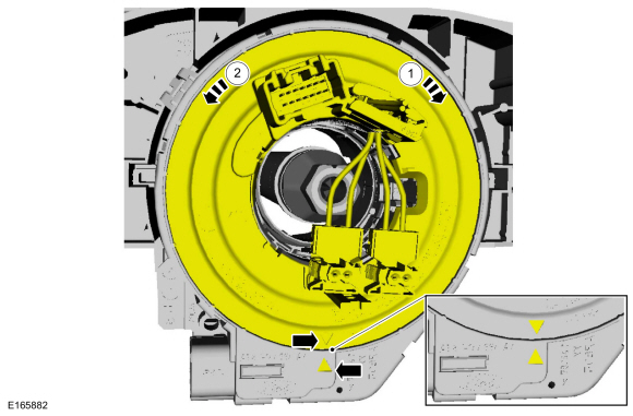
NOTE: Typical clockspring shown, others similar.
-
NOTICE: Do not over-rotate the clockspring inner rotor. The internal ribbon wire is connected to the clockspring rotor. The internal ribbon wire acts as a stop and can be broken from its internal connection. Failure to follow this instruction may result in component damage and/or system failure.
NOTE: After final positioning, do not allow the clockspring rotor to rotate from this position.
-
Turn the rotor clockwise until resistance is felt.
-
Turn the rotor counterclockwise through approximately
3.75 complete turns, until the arrow on the rotor aligns to the arrow on
the housing.
-
Turn the rotor clockwise until resistance is felt.
 |

 Inspection and Repair after a Supplemental Restraint System (SRS) Deployment. General Procedures
Inspection
WARNING:
If a vehicle has been in a crash, inspect the Restraints
Control Module (RCM) and impact sensor mounting areas for any damage or
deformation...
Other information:
Ford Fiesta 2014 - 2019 Service Manual: Pinpoint Test - DTC: I. Diagnosis and Testing
B007F:11, B007F:12, B007F:13 and B007F:1A Refer to Wiring Diagrams Cell 46 for schematic and connector information. Normal Operation and Fault Conditions The RCM continuously monitors the passenger safety belt retractor pretensioner circuits for the following faults: Resistance out of range Unexpected voltage Short to ground Faulted passe..
Ford Fiesta 2014 - 2019 Service Manual: Module Controlled Functions - Overview. Description and Operation
Body Control Module The BCM controls: Battery saver function Delayed accessory function Dimmable backlighting Exterior lighting Exterior mirrors defrost Heated seats Horn Interior lighting Luggage compartment/liftgate release Parking aid system Perimeter anti-theft alarm Power door locks Po..
Categories
- Manuals Home
- Ford Fiesta Service Manual (2014 - 2019)
- Climate Control System - General Information
- Fuel Rail. Removal and Installation
- Service Information
- Maintenance Schedules - Gasoline Engines. Description and Operation
- Engine System - General Information
Ride Height Measurement. General Procedures
Special Tool(s) / General Equipment
Surface GaugeCheck
Ride Height Measurement - Front
NOTE: Make sure that the vehicle is positioned on a flat, level surface and the tires are inflated to the correct pressure. Vehicle should have a full tank of fuel.
Ride height = 2-3Measurement 2
Measurement 3
Use the General Equipment: Surface Gauge