Ford Fiesta: Engine Cooling - 1.6L EcoBoost (132kW/180PS) – Sigma / Coolant Pump. Removal and Installation
Special Tool(s) /
General Equipment
 |
303-1556
Locking Tool, Timing Belt
TKIT-2010B-FLM
TKIT-2010B-ROW |
 |
303-748
Locking Tool, Crankshaft
TKIT-2010B-FLM
TKIT-2010B-ROW |
Removal
NOTICE:
Whenever turbocharger air intake system components are
removed, always cover open ports to protect from debris. It is important
that no foreign material enter the system. The turbocharger compressor
vanes are susceptible to damage from even small particles. All
components should be inspected and cleaned, if necessary, prior to
installation or reassembly.
-
Drain the cooling system.
Refer to: Engine Cooling System Draining, Vacuum Filling and Bleeding
(303-03B Engine Cooling - 1.6L EcoBoost (132kW/180PS) – Sigma, General
Procedures).
-
Remove the air cleaner outlet pipe.
Refer to: Air Cleaner Outlet Pipe (303-12B Intake Air Distribution and
Filtering - 1.6L EcoBoost (132kW/180PS) – Sigma, Removal and
Installation).
-
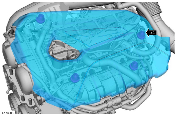
Remove the engine appearance cover.
-
-
Remove the turbocharger inlet tube retainers.
-
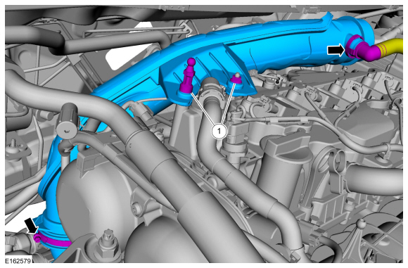
Disconnect the vent hose.
-
Loosen the clamp and remove the turbocharger inlet tube.
-
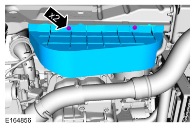
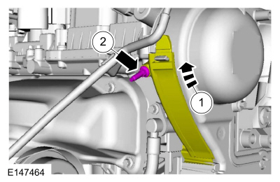
Remove the heat shield screws and the heat shield.
-
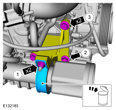
NOTE:
It may be necessary to rotate the halfshaft to remove the front lower bolt.
-
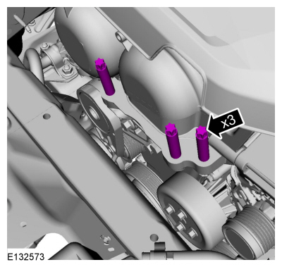
Remove the nuts and the axle bearing support.
-
Remove the bolt.
Loosen:
3 turn(s)
-
Remove the bolts.
-
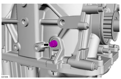
Remove the engine block bolt.
-
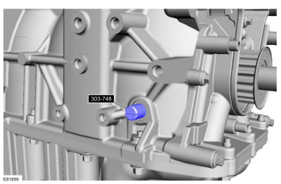
NOTE:
The Crankshaft TDC (top dead center) Timing Pin will
contact the crankshaft and prevent it from turning past TDC. However,
the crankshaft can still be rotated in the counterclockwise direction.
The crankshaft must remain at the TDC position during coolant pump
removal and installation.
Install Special Service Tool: 303-748
Locking Tool, Crankshaft.
-
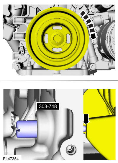
NOTICE:
Only rotate the crankshaft clockwise.
Rotate the crankshaft slowly until the crankshaft stops.
-
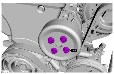
Loosen the coolant pump pulley bolts.
Loosen:
2 turn(s)
-
Remove the generator.
Refer to: Generator - 1.6L EcoBoost (132kW/180PS) – Sigma (414-02 Generator and Regulator, Removal and Installation).
-
Remove the engine mount.
Refer to: Engine Mount (303-01B Engine - 1.6L EcoBoost (132kW/180PS) – Sigma, Removal and Installation).
-
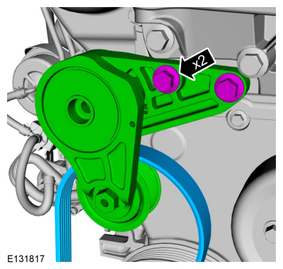
Remove the bolts and the accessory drive belt tensioner.
-
-
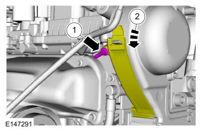
Remove the timing cover stud bolt.
-
Detach the cover from the retainer and open.
-
-
Remove the bolts and the coolant pump pulley.
-
Remove the engine mount stud.
-
Detach the wiring harness retainer.
-
Remove the wiring harness bracket bolt.
-
Detach the wiring harness retainer.
-
Remove the timing cover bolts and the timing cover.
-
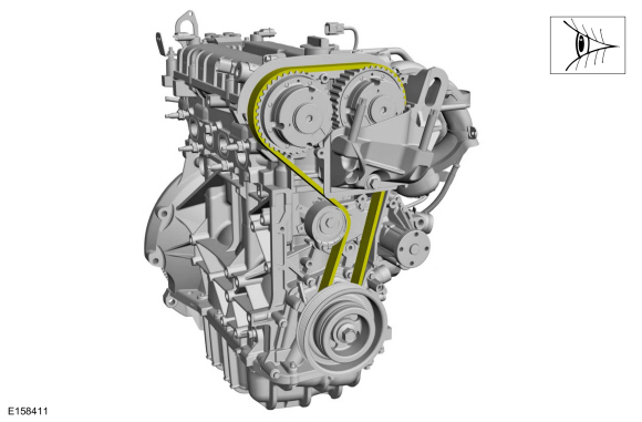
NOTICE:
Install a new timing belt if the existing belt is contaminated by coolant or oil.
Remove the timing belt.
Refer to: Timing Belt (303-01B Engine - 1.6L EcoBoost (132kW/180PS) – Sigma, Removal and Installation).
-
-
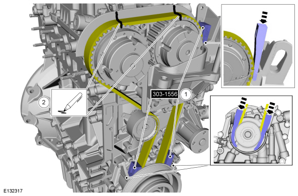
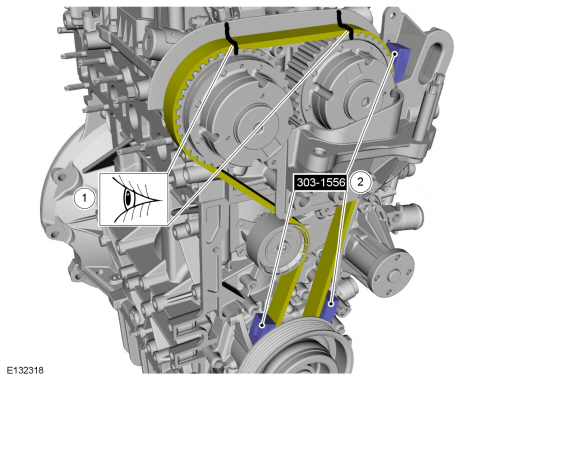
NOTICE:
Only use the specified special tool.
NOTICE:
Make sure that the crankshaft is not rotated while the special tool is installed.
Install the special service tool.
Install Special Service Tool: 303-1556
Locking Tool, Timing Belt.
-
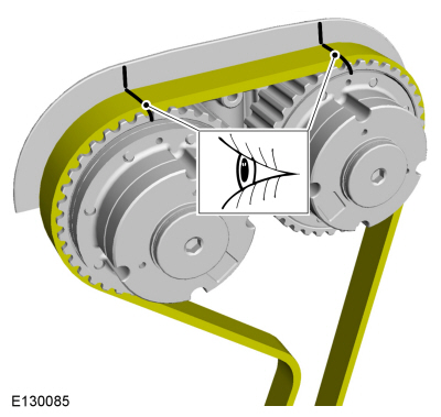
NOTICE:
Note the position of the components before removal.
Mark the position of the components before removal.
-
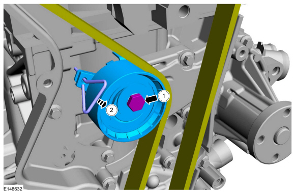
 WARNING:
Take extra care when handling the compressed spring.
WARNING:
Take extra care when handling the compressed spring.
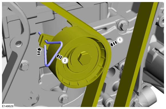
NOTICE:
The crankshaft or camshafts must not be rotated while the timing belt is removed.
Install a small screwdriver or holding pin.
Rotate the timing belt tensioner and install a holding pin.
-
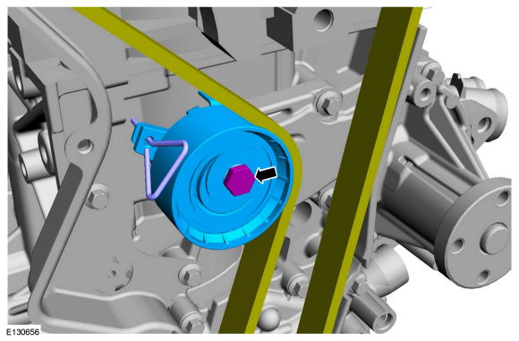
WARNING:
Take extra care when handling the compressed spring.
Remove the bolt and timing belt tensioner.
-
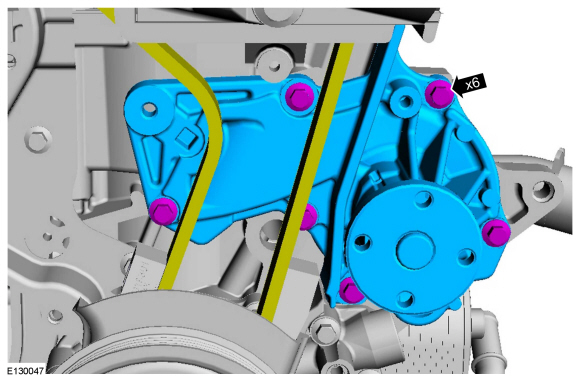
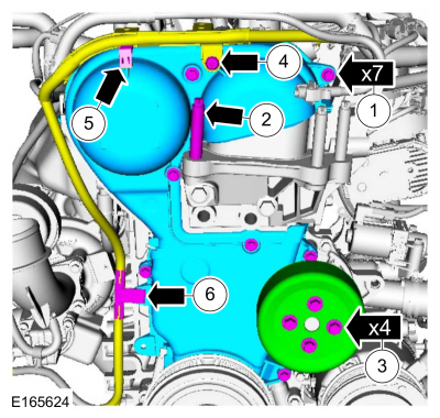
NOTICE:
Protect the timing belt and the lower timing belt cover from contamination by the coolant.
Remove the bolts and the coolant pump.
Installation
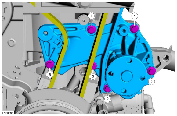
-
Install the coolant pump and tighten the bolts in the sequence order.
Torque:
89 lb.in (10 Nm)
-
NOTE:
Make sure that the components are installed to the position noted before removal.
-
WARNING:
Take extra care when handling the compressed spring.
-
Install the timing belt tensioner and tighten the bolt.
Torque:
18 lb.ft (25 Nm)
-
Remove the holding pin.
-
-
NOTE:
Make sure that the components are installed to the position noted before removal.
-
Remove Special Service Tool: 303-1556
Locking Tool, Timing Belt.
-
-
Install the timing cover and tighten the bolts.
Torque:
89 lb.in (10 Nm)
-
Finger tight.
Install the engine mount stud.
-
Finger tight.
Install the coolant pump pulley and the bolts.
-
Install and tighten the wiring harness bracket bolt.
Torque:
71 lb.in (8 Nm)
-
Attach the wiring harness retainer.
-
Attach the wiring harness retainer.
-
-
Close the cover.
-
Install and tighten the timing cover stud bolt.
Torque:
89 lb.in (10 Nm)
-
Install the accessory drive tensioner and tighten the bolts.
Torque:
35 lb.ft (48 Nm)
-
Install the engine mount studs.
Torque:
71 lb.in (8 Nm)
-
Install the engine mount.
Refer to: Engine Mount (303-01B Engine - 1.6L EcoBoost (132kW/180PS) – Sigma, Removal and Installation).
-
Install the generator.
Refer to: Generator - 1.6L EcoBoost (132kW/180PS) – Sigma (414-02 Generator and Regulator, Removal and Installation).
-
Remove the special service tool.
Remove Special Service Tool: 303-748
Locking Tool, Crankshaft.
-
Install and tighten the engine block bolt.
Torque:
177 lb.in (20 Nm)
-
NOTE:
Make sure that a new component is installed.
-
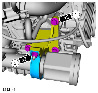
Position the support bracket and tighten the bolts.
Torque:
35 lb.ft (48 Nm)
-
Install the axle bearing support and tighten the nuts.
Torque:
Stage 1:
44 lb.in (5 Nm)
Stage 2:
18 lb.ft (25 Nm)
Stage 3:
18 lb.ft (25 Nm)
-
Install the heat shield and tighten the screws.
-
Tighten the coolant pump pulley bolts.
Torque:
177 lb.in (20 Nm)
-
-
Install the turbocharger inlet tube retainers.
-
Install the turbocharger inlet tube and tighten the clamp.
-
Install the engine appearance cover.
-
Install the air cleaner outlet pipe.
Refer to: Air Cleaner Outlet Pipe (303-12B Intake Air Distribution and
Filtering - 1.6L EcoBoost (132kW/180PS) – Sigma, Removal and
Installation).
-
Fill and bleed the cooling system.
Refer to: Engine Cooling System Draining, Vacuum Filling and Bleeding
(303-03B Engine Cooling - 1.6L EcoBoost (132kW/180PS) – Sigma, General
Procedures).
Special Tool(s) /
General Equipment
Hose Clamp Remover/Installer
Removal
NOTE:
Removal steps in this procedure may contain installation details...
Removal
NOTE:
Removal steps in this procedure may contain installation details.
Drain the cooling system.
Refer to: Engine Cooling System Draining, Vacuum Filling and Bleeding
(303-03B Engine Cooling - 1...
Other information:
Special Tool(s) /
General Equipment
Air Body Saw
Removal
NOTICE:
The production muffler and tailpipe assembly is one-piece
construction. The service muffler and tailpipe is 2-piece construction.
It is necessary to cut the production exhaust system to enable the
service section(s) to be fitted...
U0253:00
Normal Operation and Fault Conditions
The RCM uses information contained in messages from the APIM sent on the HS-CAN .
DTC Fault Trigger Conditions
DTC
Description
Fault Trigger Conditions
U0253:00
Lost Communication with Accessory Protocol Interface M..
Categories
Special Tool(s) /
General Equipment
Master Cylinder Bleeding Set
Bleeding
NOTICE:
If the fluid is spilled on the paintwork, the affected area must be immediately washed down with cold water.
Master Cylinder
NOTE:
When a new brake master cylinder has been installed, it
should be primed to prevent air from entering the system.
NOTE:
Make sure the area around the master cylinder cap is clean and free of foreign material.
Remove the brake fluid reservoir cap.
read more

 Coolant Bypass Solenoid Valve. Removal and Installation
 Coolant Shutoff Solenoid Valve. Removal and Installation