Ford Fiesta: Climate Control System - General Information / Refrigerant System Tests - 1.6L EcoBoost (132kW/180PS) – Sigma. General Procedures
Inspection
NOTE: Procedure 1 — Ambient Temperature between 21°C (70°F) and 38°C (100°F)
NOTE: Variable compressors may not stroke up unless the ambient temperatures are above 21°C (70°F) when conducting the pressure mapping procedure. Variable compressor need to see a thermal load on the system in order to create normal operating pressures.
-
Run the engine until it reaches normal operating temperature.
-
Connect the air conditioning service unit to the refrigerant system.
-
Set temperature to the lowest possible temperature
setting with the dual function disabled (if equipped). Manually set
blower on HI. If the vehicle has a fresh air/recirc button, set it to
FRESH. If the vehicle has an A/C switch or compressor on switch, set it to A/C ON.
-
Open all vehicle windows and leave the hood open for the test. Open the rear doors.
-
Confirm the compressor is operating and the engine
cooling fan(s) are operating or engaged. Allow the vehicle to idle until
the suction (low-side) and discharge (high-side) pressures are stable
or fluctuate in a range that repeats.
-
Record the ambient (shop) temperature.
-
Record the discharge pressure. If the pressure is fluctuating, record the average value.
-
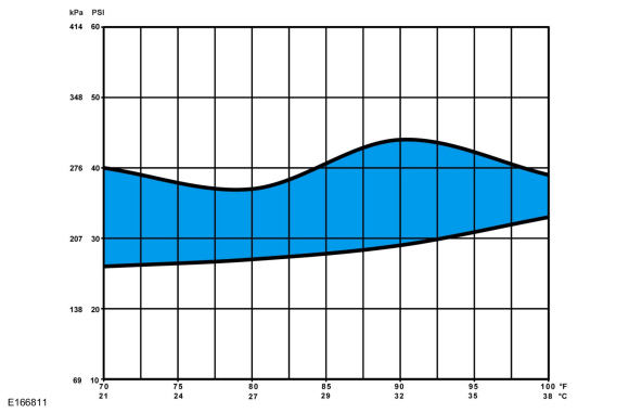
Determine if the discharge pressure falls within the normal operating limits using the Normal Refrigerant Discharge Pressures 21 - 38° C (70 - 100° F) Ambient (30 - 60% Relative Humidity) chart below.
 |
-
Record the suction pressure. If the pressure is fluctuating, record the average value.
-
Determine if the suction pressure falls within the normal operating limits using the Normal Refrigerant Suction Pressures 21 - 38° C (70 - 100° F) Ambient (30 - 60% Relative Humidity) chart below.
 |
-
NOTE: Use the following table to guide diagnosis of the refrigerant system if operating pressures are outside normal limits.
Refer to the chart below.High (Discharge) Pressure Low (Suction) Pressure Component — Causes High Normal to High - Condenser — inadequate airflow.
- Engine — overheating.
Normal to High Normal - Refrigerant overcharge — air in refrigerant.
Normal to Low High - A/C Compressor — low performance.
Normal to Low Normal to High - A/C suction line — partially restricted or plugged. a
Normal to Low Low - Low refrigerant charge — leak in system.
- A/C suction line — partially restricted or plugged. b
Erratic Operation or Compressor Not Running - Ambient Air Temperature (AAT) sensor — poor connection.
- A/C pressure transducer — poor connection.
- Evaporator temperature sensor — poor connection.
- Low refrigerant charge — leak in system.
Additional Possible Components or Causes Associated With Inadequate Compressor Operation - Compressor drive belt — loose
- Compressor clutch — slipping
- Clutch coil open — shorted, or loose mounting
- Control assembly switch — dirty contacts or sticking open
- Clutch wiring circuit — high resistance, open or blown fuse
- Compressor operation interrupted by engine computer
Additional Possible Components or Causes Associated With a Damaged Compressor - Incorrect clutch air-gap
- Suction accumulator — refrigerant oil bleed hose plugged
- Refrigerant leaks
a Low pressure reading will be normal to high if restriction is downstream of service access valve.
b Low pressure reading will be low if restriction is upstream of service access valve.
Inspection
NOTE: Procedure 2 — Ambient Temperature Above 38°C (100°F)
-
Run the engine until it reaches normal operating temperature.
-
Connect the air conditioning service unit to the refrigerant system.
-
Set temperature to the lowest possible temperature
setting with the dual function disabled (if equipped). Manually set
blower on HI. If the vehicle has a fresh air/recirc button, set it to
FRESH. If the vehicle has an A/C switch or compressor on switch, set it to A/C ON.
-
Open all vehicle windows and leave the hood open for the
test. Open the rear hatch and/or rear doors (if equipped).
-
Confirm the compressor is operating and the engine
cooling fan(s) are operating or engaged. Allow the vehicle to idle until
the suction (low-side) and discharge (high-side) pressures are stable
or fluctuate in a range that repeats.
-
Record the ambient (shop) temperature.
-
Record the discharge pressure. If the pressure is fluctuating, record the average value.
-
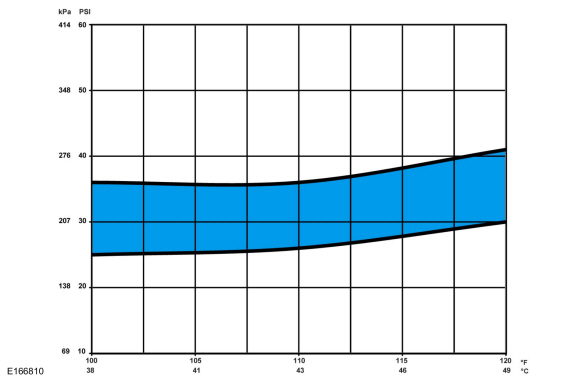
Determine if the discharge pressure falls within the normal operating limits using the Normal Refrigerant Discharge Pressures 38 - 49° C (100 - 120° F) Ambient (15 - 40% Relative Humidity) chart below.
 |
-
Record the suction pressure. If the pressure is fluctuating, record the average value.
-
Determine if the suction pressure falls within the normal operating limits using the Normal Refrigerant Suction Pressures 38 - 49° C (100 - 120° F) Ambient (15 - 40% Relative Humidity) chart below.
 |
-
NOTE: Use the following table to guide diagnosis of the refrigerant system if operating pressures are outside normal limits.
Refer to the chart below.High (Discharge) Pressure Low (Suction) Pressure Component — Causes High Normal to High - Condenser — inadequate airflow.
- Engine — overheating.
Normal to High Normal - Refrigerant overcharge — air in refrigerant.
Normal to Low High - A/C Compressor — low performance.
Normal to Low Normal to High - A/C suction line — partially restricted or plugged. a
Normal to Low Low - Low refrigerant charge — leak in system.
- A/C suction line — partially restricted or plugged. b
Erratic Operation or Compressor Not Running - Ambient Air Temperature (AAT) sensor — poor connection.
- A/C pressure transducer — poor connection.
- Evaporator temperature sensor — poor connection.
- Low refrigerant charge — leak in system.
Additional Possible Components or Causes Associated With Inadequate Compressor Operation - Compressor drive belt — loose
- Compressor clutch — slipping
- Clutch coil open — shorted, or loose mounting
- Control assembly switch — dirty contacts or sticking open
- Clutch wiring circuit — high resistance, open or blown fuse
- Compressor operation interrupted by engine computer
Additional Possible Components or Causes Associated With a Damaged Compressor - Incorrect clutch air-gap
- Suction accumulator — refrigerant oil bleed hose plugged
- Refrigerant leaks
a Low pressure reading will be normal to high if restriction is downstream of service access valve.
b Low pressure reading will be low if restriction is upstream of service access valve.
 Refrigerant Oil Adding. General Procedures
Special Tool(s) /
General Equipment
Air Conditioning Service Unit
Refrigerant Oil Injector Set
Filling
Adjust the oil injector piston and fill the oil
injector with the correct amount of clean, new Motorcraft® PAG
Refrigerant Compressor Oil (YN-12-D)...
 Air Conditioning (A/C) Clutch and Air Conditioning (A/C) Clutch Field Coil. Removal and Installation
Special Tool(s) /
General Equipment
412-134Holding Tool, Compressor ClutchTKIT-2006U-F/FMTKIT-2006U-FLM/LMTKIT-2006U-ROW1TKIT-2006U-ROW2
Removal
NOTE:
Removal steps in this procedure may contain installation details...
Other information:
Ford Fiesta 2014 - 2019 Service Manual: B-Pillar and Reinforcement. Removal and Installation
Special Tool(s) / General Equipment Resistance Spotwelding Equipment 8 mm Drill Bit MIG/MAG Welding Equipment Spot Weld Drill Bit Locking Pliers Removal NOTICE: The B-pillar inner reinforcement is constructed of boron steel and cannot be sectioned...
Ford Fiesta 2014 - 2019 Service Manual: Pinpoint Test - DTC: U. Diagnosis and Testing
B1414:11, B1414:93, B1419:11, B1419:93 Refer to Wiring Diagrams Cell 46 for schematic and connector information. Normal Operation and Fault Conditions The RCM monitors the driver front door and RH C-pillar side impact sensors and circuits for the following faults: Open circuit Short to voltage Short to ground Faulted driver front door ..
Categories
- Manuals Home
- Ford Fiesta Service Manual (2014 - 2019)
- Camshafts. Removal and Installation
- Engine
- Maintenance Schedules
- Body Control Module (BCM). Removal and Installation
- Service Information
Component Bleeding. General Procedures
Special Tool(s) / General Equipment
Master Cylinder Bleeding SetBleeding
NOTICE: If the fluid is spilled on the paintwork, the affected area must be immediately washed down with cold water.
Master Cylinder
NOTE: When a new brake master cylinder has been installed, it should be primed to prevent air from entering the system.
NOTE: Make sure the area around the master cylinder cap is clean and free of foreign material.
Remove the brake fluid reservoir cap.