Ford Fiesta: Brake System - General Information / Brake System Pressure Bleeding. General Procedures
Special Tool(s) / General Equipment
| Brake/Clutch System Pressure Bleeder/Filler | |
| Fluid Container |
Bleeding
All vehicles
NOTICE: If the fluid is spilled on the paintwork, the affected area must be immediately washed down with cold water.
NOTE: The HCU bleeding procedure and a second brake system pressure bleed must be carried out if a new HCU has been installed.
-
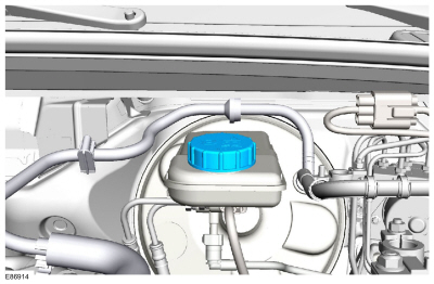
NOTE: Make sure the area around the master cylinder cap is clean and free of foreign material.
Remove the brake fluid reservoir cap.
 |
-
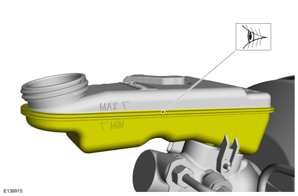
Make sure the fluid reservoir is filled with clean specified brake fluid.
Refer to: Specifications (206-00 Brake System - General Information, Specifications).
 |
-
-
NOTE: Master cylinder pressure bleeder adapter tools are available from various manufacturers of pressure bleeding equipment. Follow the instructions of the manufacturer when installing the adapter.
Install the bleeder adapter to the brake master cylinder reservoir and attach the bleeder tank hose to the fitting on the adapter.
Use the General Equipment: Brake/Clutch System Pressure Bleeder/Filler
-
NOTE: Make sure the bleeder tank contains enough clean, specified brake fluid to complete the bleeding operation.
Open the valve on the bleeder tank and apply 207-345 kPa (30-50 psi) to the brake system.
-
-
With the vehicle in NEUTRAL, position it on a hoist.
Refer to: Jacking and Lifting - Overview (100-02 Jacking and Lifting, Description and Operation).
-
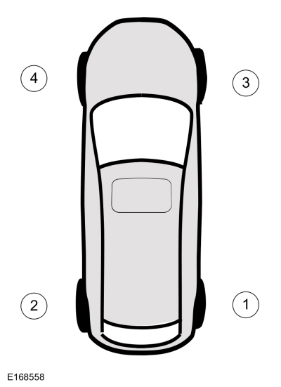
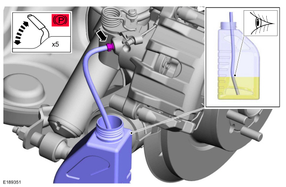
Bleeding steps must be followed in the order indicated in the graphic.
 |
-
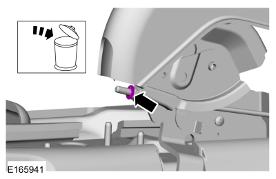
If equipped, remove the bleeder screw cap.
 |
-
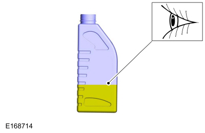
Partially fill a clean brake fluid container with clean specified brake fluid.
Refer to: Specifications (206-00 Brake System - General Information, Specifications).
Use the General Equipment: Fluid Container
 |
-
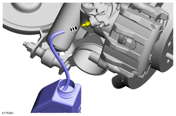
Submerge a hose into the brake fluid in the container and connect the hose to bleeder screw.
 |
-
-
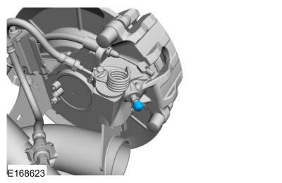
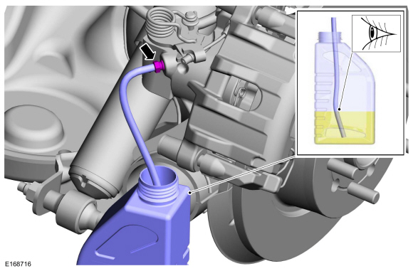
Loosen the bleeder screw.
Loosen:
: 180°
-
Leave open until clear, bubble-free brake fluid flows, then tighten the bleeder screw.
-
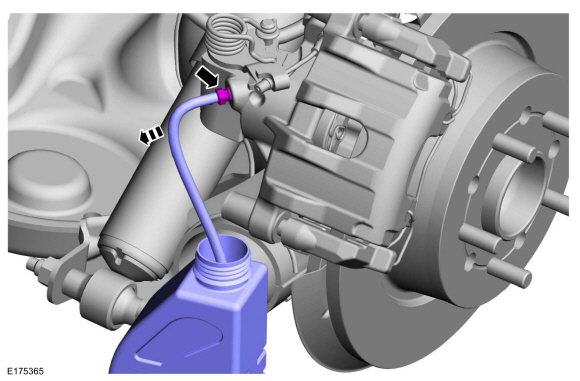
Loosen the bleeder screw.
 |
-
-
Disconnect the hose and tighten the bleeder screw to specification.
Refer to: Specifications (206-00 Brake System - General Information, Specifications).
-
Disconnect the hose and tighten the bleeder screw to specification.
 |
-
Repeat steps 8-10 at the remaining wheel ends.
Vehicles with rear integral parking brake calipers
-
NOTE: Due to the complexity of the fluid path within the rear integral parking brake calipers, it is necessary to apply and release the parking brake during the bleed procedure.
-
Apply and release the parking brake 5 times.
-
Loosen the bleeder screw.
Loosen: 180°
-
Leave open until clear, bubble-free fluid flows and then tighten the bleeder screw to specification.
Refer to: Specifications (206-00 Brake System - General Information, Specifications).
-
Repeat as necessary.
-
Apply and release the parking brake 5 times.
 |
All vehicles
-
If equipped, install the bleeder screw cap.
|
-
Lower the vehicle.
-
Close the bleeder tank valve and release the pressure.
Remove the General Equipment: Brake/Clutch System Pressure Bleeder/Filler
-
Fill the reservoir with clean, specified brake fluid.
Refer to: Specifications (206-00 Brake System - General Information, Specifications).
|
-
Install the brake fluid reservoir cap.
|
Vehicles with new hydraulic control unit (HCU) installed
NOTE: The HCU bleeding procedure and a second brake system pressure bleed must be carried out if a new HCU has been installed.
-
Using the diagnostic scan tool, follow the ABS Service Bleed instructions.
-
Repeat brake system pressure bleeding steps.
 Brake System Inspection. General Procedures
Materials
Name
Specification
Motorcraft® Silicone Brake Caliper Grease and Dielectric CompoundXG-3-A
ESA-M1C200-AESE-M1C171-A
Inspection
Brake Pads
Inspect the brake pads for contamination...
 Drum Brake
..
Other information:
Ford Fiesta 2014 - 2019 Service Manual: Pinpoint Test - DTC: GG. Diagnosis and Testing
B0061:11, B0061:12, B0061:13, B0061:64 Refer to Wiring Diagrams Cell 46 for schematic and connector information. Normal Operation and Fault Conditions The Belt Tension Sensor (BTS) operates in conjunction with the OCS . The OCS interprets a variable voltage signal provided by the Belt Tension Sensor (BTS) to identify the possible presence of a child safety seat in the front pa..
Ford Fiesta 2014 - 2019 Service Manual: Crankshaft Front Seal. Removal and Installation
Special Tool(s) / General Equipment 100-001 (T50T-100-A) Slide Hammer 303-175 (T82L-6316-A) Installer, Crankshaft Vibration DamperTKIT-1982-F 303-335 (T88T-6701-A) Installer, Front Cover Oil SealTKIT-1988-FLMTKIT-1988-F 303-420 (T92P-6701-BH) Installer, Crankshaft Front Oil SealTKIT-1992-FLMH/LMHTKIT-1992-LMH/MH 308-375Remover..
Categories
- Manuals Home
- Ford Fiesta Service Manual (2014 - 2019)
- Engine. Assembly
- Engine - 1.6L EcoBoost (132kW/180PS) – Sigma
- Manual Transmission - 6-Speed Manual Transmission – B6
- Manual Transmission, Clutch, Transfer Case and Power Transfer Unit
- Engine
Parking Brake Control. Removal and Installation
Removal
NOTE: Removal steps in this procedure may contain installation details.
Remove the floor console.Refer to: Floor Console (501-12 Instrument Panel and Console, Removal and Installation).
Remove the driver seat.
Refer to: Front Seat (501-10 Seating, Removal and Installation).
Remove the parking brake cable adjustment lock nut.
 Loosen the parking brake cable adjustment nut.