Ford Fiesta: Front Suspension / Wheel Studs. Removal and Installation
Special Tool(s) / General Equipment
 |
211-001
(TOOL-3290-D)
Remover, Tie-Rod End |
Removal
NOTICE: Suspension fasteners are critical parts that affect performance of vital components and systems. Failure of these fasteners may result in major service expense. Use the same or equivalent parts if replacement is necessary. Do not use a replacement part of lesser quality or substitute design. Tighten fasteners as specified.
-
Remove the brake disc.
Refer to: Brake Disc (206-03 Front Disc Brake, Removal and Installation).
-
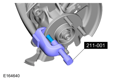
Remove the wheel stud.
Use Special Service Tool: 211-001 (TOOL-3290-D) Remover, Tie-Rod End.
 |
Installation
-
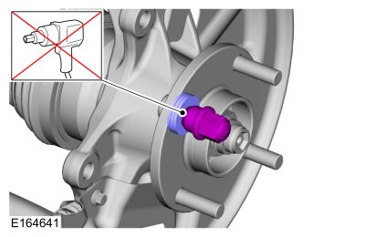
NOTE: Make sure to use washers that have an ID that is larger than the OD of the wheel stud serrations. Use enough washers (approximately 3 to 4) to allow the wheel stud to fully seat against the hub flange.
-
Position the wheel stud in the flange, making sure
the serrations on the stud line up with the serrations in the flange.
Install the washers and a wheel nut.
-
Remove the wheel nut and the washers. Discard the wheel nut.
-
Position the wheel stud in the flange, making sure
the serrations on the stud line up with the serrations in the flange.
Install the washers and a wheel nut.
 |
-
Install the brake disc.
Refer to: Brake Disc (206-03 Front Disc Brake, Removal and Installation).
 Wheel Knuckle. Removal and Installation
Special Tool(s) /
General Equipment
204-161
(T97P-1175-A)
Installer, HalfshaftTKIT-1997-LM2TKIT-1997-F/FM2TKIT-1997-FLM2
205-D070
(D93P-1175-B)
Remover, Front Wheel Hub
Tie Rod End Remover
Removal
NOTICE:
Suspension fasteners are critical parts that affect
performance of vital components and systems...
 Front Strut and Spring Assembly. Disassembly and Assembly
Special Tool(s) /
General Equipment
Spring Compressor
Vise
Materials
Name
Specification
Motorcraft® Silicone Brake Caliper Grease and Dielectric CompoundXG-3-A
ESA-M1C200-AESE-M1C171-A
DISASSEMBLY
WARNING:
Coil springs and strut assemblies are compressed under
extreme load...
Other information:
Ford Fiesta 2014 - 2019 Service Manual: Instrument Panel. Removal and Installation
Special Tool(s) / General Equipment Hose Clamp(s) Removal NOTE: Removal steps in this procedure may contain installation details. Vehicles with air conditioning Recover the refrigerant. Refer to: Air Conditioning (A/C) System Recovery, Evacuation and Charging (412-00 Climate Control System - General Information) ...
Ford Fiesta 2014 - 2019 Service Manual: Trough Assembly. Removal and Installation
Special Tool(s) / General Equipment Interior Trim Remover Removal NOTE: Removal steps in this procedure may contain installation details. Remove the roof opening panel glass. Refer to: Roof Opening Panel Glass (501-17 Roof Opening Panel, Removal and Installation)...
Categories
- Manuals Home
- Ford Fiesta Service Manual (2014 - 2019)
- Engine Component View. Description and Operation
- Timing Belt. Removal and Installation
- Engine System - General Information
- Maintenance Schedules - Gasoline Engines. Description and Operation
- Manual Transmission, Clutch, Transfer Case and Power Transfer Unit
Component Bleeding. General Procedures
Special Tool(s) / General Equipment
Master Cylinder Bleeding SetBleeding
NOTICE: If the fluid is spilled on the paintwork, the affected area must be immediately washed down with cold water.
Master Cylinder
NOTE: When a new brake master cylinder has been installed, it should be primed to prevent air from entering the system.
NOTE: Make sure the area around the master cylinder cap is clean and free of foreign material.
Remove the brake fluid reservoir cap.