Ford Fiesta: Instrument Panel and Console / Instrument Panel. Removal and Installation
Special Tool(s) / General Equipment
| Hose Clamp(s) |
Removal
NOTE: Removal steps in this procedure may contain installation details.
Vehicles with air conditioning
-
Recover the refrigerant.
Refer to: Air Conditioning (A/C) System Recovery, Evacuation and Charging (412-00 Climate Control System - General Information) .
All vehicles
-
Remove the cowl panel grille.
Refer to: Cowl Panel Grille (501-02 Front End Body Panels, Removal and Installation).
-
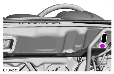
NOTE: Windshield wiper motor assembly shown removed for clarity.
NOTE: Access the bolt through the arm of the windshield wiper assembly.
Remove the bolt.
Torque: 18 lb.ft (25 Nm)
 |
-
Remove the evaporator pipe studbolt, position the flange and pipe aside.
Torque: 133 lb.in (15 Nm)
 |
-
NOTE: Make sure all the coolant openings are sealed, or coolant may leak into the vehicle when the instrument panel is removed.
-
Install hose clamping pliers on the coolant hoses.
Use the General Equipment: Hose Clamp(s)
-
Release the clamp and disconnect the coolant hose.
-
Depress the tab and disconnect the coolant hose.
-
Remove the nut.
Torque: 9 lb.in (1 Nm)
-
Install hose clamping pliers on the coolant hoses.
 |
Vehicles without air conditioning
-
NOTE: Make sure all the coolant openings are sealed, or coolant may leak into the vehicle when the instrument panel is removed.
-
Install hose clamping pliers on the coolant hoses.
Use the General Equipment: Hose Clamp(s)
-
Release the clamp and disconnect the coolant hose.
-
Depress the tab and disconnect the coolant hose.
-
Remove the nut.
Torque: 9 lb.in (1 Nm)
-
Install hose clamping pliers on the coolant hoses.
 |
All vehicles
-
Remove the driver side front door.
Refer to: Front Door (501-03 Body Closures, Removal and Installation).
-
Remove the driver seat.
Refer to: Front Seat (501-10 Seating, Removal and Installation).
Vehicles with automatic transmission
-
Remove the selector lever assembly.
Refer to: Selector Lever Assembly (307-05 Automatic Transmission External Controls - 6-Speed PowerShift Transmission – DPS6/6DCT250, Removal and Installation).
Vehicles with manual transmission
-
Remove the gearshift lever.
Refer to: Gearshift Lever (308-06 Manual Transmission External Controls - 5-Speed Manual Transmission – B5/IB5/6-Speed Manual Transmission – B6, Removal and Installation).
All vehicles
-
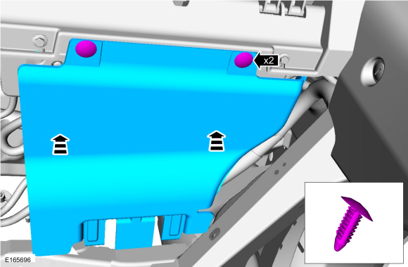
Remove the retainers and the RH insulation panel.
 |
-
Release the retaining tabs and remove the glove compartment.
 |
-
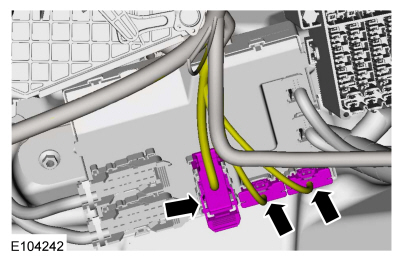
Disconnect the electrical connectors.
 |
-
On both sides, remove the A-pillar trim panel.
Refer to: A-Pillar Trim Panel (501-05 Interior Trim and Ornamentation, Removal and Installation).
-
On both sides.
Position the front door weatherstrip aside, release the clips and remove the instrument panel finish panel.
 |
-
On both sides.
Position the front door weatherstrip aside, remove the push-pins, the scuff plate and the lower cowl trim panel.
 |
-
Disconnect the electrical connector.
 |
-
Disconnect the electrical connector.
 |
-
NOTICE: Do not allow the steering wheel to rotate while the steering column shaft is disconnected, or damage to the clockspring may result. If there is evidence that the shaft has rotated, remove and recenter the clockspring. For additional information, refer to Section 501-20B.
-
-
Remove the bolt and disconnect the steering column shaft.
Torque: 21 lb.ft (28 Nm)
-
Disconnect the electrical connector and position the wiring harness aside.
-
Release the tabs and position the hood latch release handle aside.
-
Remove the bolt and disconnect the steering column shaft.
 |
-
 WARNING:
Turn the ignition OFF and wait one minute to
deplete the backup power supply. Ignition must remain OFF until repair
is complete. Failure to follow this instruction may result in serious
personal injury or death in the event of an accidental deployment.
-
Remove the bolts, detach the wiring harness retainers and remove the instrument panel center brace.
Torque: 18 lb.ft (25 Nm)
-
Disconnect the electrical connectors, detach the wiring retainers and position the wiring harness aside.
-
Remove the bolts, detach the wiring harness retainers and remove the instrument panel center brace.
 |
-
Remove the A-pillar to in-vehicle cross beam support bolt and the plug.
Torque: 18 lb.ft (25 Nm)
 |
-
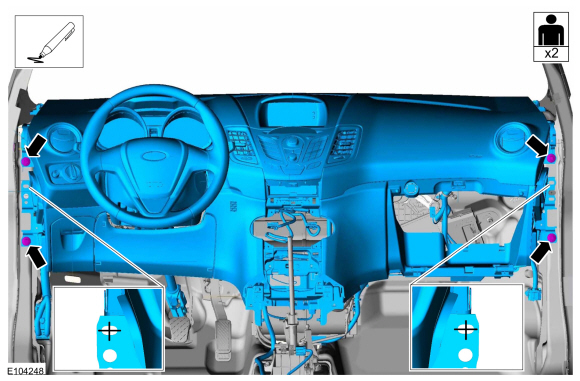
NOTE: To avoid damage to the instrument panel, this step requires the help of an assistant.
NOTE: Make sure that all electrical connectors and wiring are not hindered before removing the instrument panel or damage to the components may occur.
Index-mark the instrument panel location to aid in instrument panel installation, remove the instrument panel support bolts and the instrument panel.
Torque: 18 lb.ft (25 Nm)
 |
Installation
-
To install, reverse the removal procedure.
-
Fill and bleed the cooling system.
Refer to: Engine Cooling System Draining, Vacuum Filling and Bleeding (303-03B Engine Cooling - 1.6L EcoBoost (132kW/180PS) – Sigma, General Procedures).
Refer to: Engine Cooling System Draining, Vacuum Filling and Bleeding (303-03A Engine Cooling - 1.6L Duratec-16V Ti-VCT (88kW/120PS) – Sigma, General Procedures).
 Floor Console. Removal and Installation
Special Tool(s) /
General Equipment
Interior Trim Remover
Removal
NOTE:
Removal steps in this procedure may contain installation details...
 Instrument Panel Upper Section. Removal and Installation
Special Tool(s) /
General Equipment
Interior Trim Remover
Removal
All vehicles
NOTE:
Removal steps in this procedure may contain installation details...
Other information:
Ford Fiesta 2014 - 2019 Service Manual: Headlamp Switch. Removal and Installation
Special Tool(s) / General Equipment Interior Trim Remover Removal NOTE: Use a non-marring tool. Release and position the headlamp switch. Use the General Equipment: Interior Trim Remover Disconnect the electrical connector and remove the headlamp switch...
Ford Fiesta 2014 - 2019 Service Manual: Starting System - System Operation and Component Description. Description and Operation
System Diagram Item Description 1 PCM 2 Starter Relay 3 Starter Motor 4 BCM 5 Ignition Switch - Push Button Start 6 RFA 7 Clutch Pedal Switch 8 Brake Switch System Operation Network Message Chart Module Network Input Messages Powertrain Control Module (PCM) ..
Categories
- Manuals Home
- Ford Fiesta Service Manual (2014 - 2019)
- Camshafts. Removal and Installation
- General Information
- Engine System - General Information
- Clutch - 6-Speed Manual Transmission – B6
- Engine - 1.6L EcoBoost (132kW/180PS) – Sigma
Brake Master Cylinder. Removal and Installation
Removal
NOTICE: If the fluid is spilled on the paintwork, the affected area must be immediately washed down with cold water.
NOTE: Removal steps in this procedure may contain installation details.
All vehicles
Remove the battery tray.Refer to: Battery Tray - 1.6L Duratec-16V Ti-VCT (88kW/120PS) – Sigma (414-01 Battery, Mounting and Cables, Removal and Installation).
Refer to: Battery Tray - 1.6L EcoBoost (132kW/180PS) – Sigma (414-01 Battery, Mounting and Cables, Removal and Installation).
Disconnect the vacuum tube from the brake booster and detach the routing clip.
