Ford Fiesta: Front Suspension / Wheel Knuckle. Removal and Installation
Special Tool(s) / General Equipment
 |
204-161
(T97P-1175-A)
Installer, Halfshaft TKIT-1997-LM2 TKIT-1997-F/FM2 TKIT-1997-FLM2 |
 |
205-D070
(D93P-1175-B)
Remover, Front Wheel Hub |
| Tie Rod End Remover | |
Removal
NOTICE: Suspension fasteners are critical parts that affect performance of vital components and systems. Failure of these fasteners may result in major service expense. Use the same or equivalent parts if replacement is necessary. Do not use a replacement part of lesser quality or substitute design. Tighten fasteners as specified.
-
Remove the wheel and tire.
Refer to: Wheel and Tire (204-04A Wheels and Tires, Removal and Installation).
-
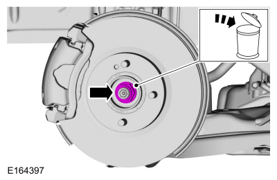
NOTE: Apply the brake to prevent the halfshaft from rotating while loosening the wheel hub nut.
Remove and discard the wheel hub nut.
 |
-
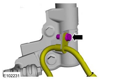
Remove the brake hose bracket bolt and position the brake hose aside.
 |
-
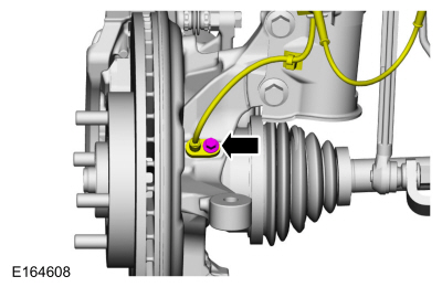
Remove the bolt and position aside wheel speed sensor.
 |
-
NOTICE: Do not use a hammer to separate the outer tie-rod end from the wheel knuckle or damage to the wheel knuckle may result.
NOTICE: Use care when installing the tie rod separator or damage to the outer tie-rod end boot may occur.
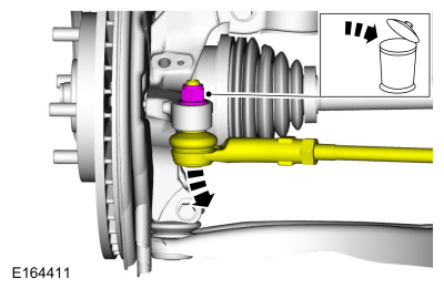
Remove and discard the tie rod end nut and disconnect the tie rod end from the wheel knuckle.
Use the General Equipment: Tie Rod End Remover
 |
-
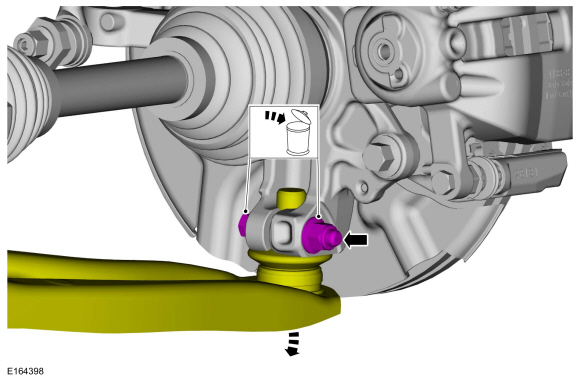
NOTICE: Do not use a prying device or separator fork between the ball joint and the wheel knuckle. Damage to the ball joint or ball joint seal may result. Only use the pry bar by inserting it into the lower arm body opening.
NOTICE: Use care when releasing the lower arm and wheel knuckle into the resting position or damage to the ball joint seal may result.
Remove and discard the ball joint pinch bolt and nut and separate the lower arm from the wheel knuckle.
 |
-
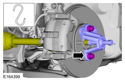
NOTICE: Do not bend the inner joint more than 18 degrees and the outer joint more than 45 degrees. Damage to the shaft will occur.
Using the special tool, press the halfshaft from the wheel bearing and hub. Support the halfshaft in a level position.
Use Special Service Tool: 205-D070 (D93P-1175-B) Remover, Front Wheel Hub.
 |
-
Remove the brake disc.
Refer to: Brake Disc (206-03 Front Disc Brake, Removal and Installation).
-
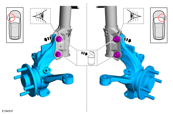
Remove and discard the front strut and spring
assembly-to-wheel knuckle bolts and nuts and remove the wheel knuckle.
 |
Installation
-
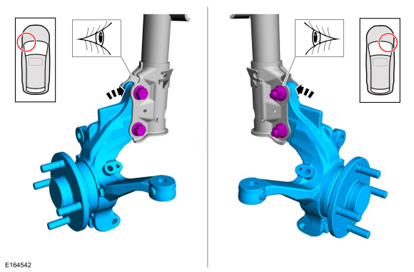
Install the wheel knuckle and install the new front strut and spring assembly-to-wheel knuckle bolts and nuts.
 |
-
Install the brake disc.
Refer to: Brake Disc (206-03 Front Disc Brake, Removal and Installation).
-
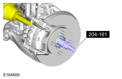
Using special tools, install the halfshaft into the wheel bearing and hub.
Use Special Service Tool: 204-161 (T97P-1175-A) Installer, Halfshaft.
 |
-
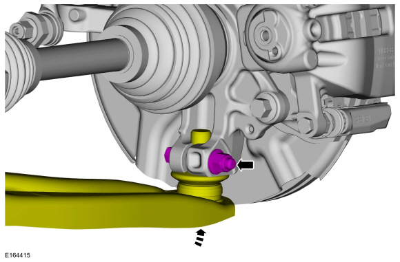
Attach the lower arm to the wheel knuckle and install the new ball joint pinch bolt and nut.
Torque: 38 lb.ft (52 Nm)
 |
-
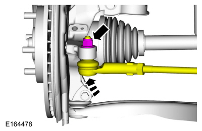
Attach the tie rod end to the wheel knuckle and install the new tie rod end nut.
Torque: 39 lb.ft (53 Nm)
 |
-
Position the wheel speed sensor and install the bolt.
Torque: 80 lb.in (9 Nm)
 |
-
Position the brake hose and install the brake hose bracket bolt.
Torque: 19 lb.ft (26 Nm)
 |
-
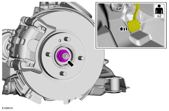
NOTE: Apply the brake to prevent the halfshaft from rotating while loosening the wheel hub nut.
Install the wheel hub nut.
Torque: 188 lb.ft (255 Nm)
 |
-
Install the wheel and tire.
Refer to: Wheel and Tire (204-04A Wheels and Tires, Removal and Installation).
-
Check and if necessary adjust front toe.
Refer to: Front Toe Adjustment (204-00 Suspension System - General Information, General Procedures).
 Wheel Hub. Removal and Installation
Removal
Refer to: Front Wheel Bearing (204-01 Front Suspension, Removal and Installation).
Installation
Refer to: Front Wheel Bearing (204-01 Front Suspension, Removal and Installation)...
 Wheel Studs. Removal and Installation
Special Tool(s) /
General Equipment
211-001
(TOOL-3290-D)
Remover, Tie-Rod End
Removal
NOTICE:
Suspension fasteners are critical parts that affect
performance of vital components and systems...
Other information:
Ford Fiesta 2014 - 2019 Service Manual: Gearshift Cable Adjustment - 5-Speed Manual Transmission – B5/IB5. General Procedures
Adjustment Position the gearshift in N position. With the vehicle in N , position it on a hoist. Refer to: Jacking and Lifting - Overview (100-02 Jacking and Lifting, Description and Operation)...
Ford Fiesta 2014 - 2019 Service Manual: Flywheel Inspection - 1.6L EcoBoost (132kW/180PS) – Sigma. General Procedures
Inspection NOTE: Do not clean the dual mass flywheel with compressed air. NOTE: Do not clean the dual mass flywheel with any kind of fluid, use a dry cloth only or damage to the dual mass flywheel may occur. NOTE: Do not clean the gap between the primary and secondary mass...
Categories
- Manuals Home
- Ford Fiesta Service Manual (2014 - 2019)
- Front Subframe. Removal and Installation
- General Information
- Fuel Rail. Removal and Installation
- Timing Belt. Removal and Installation
- Climate Control System - General Information
Brake Master Cylinder. Removal and Installation
Removal
NOTICE: If the fluid is spilled on the paintwork, the affected area must be immediately washed down with cold water.
NOTE: Removal steps in this procedure may contain installation details.
All vehicles
Remove the battery tray.Refer to: Battery Tray - 1.6L Duratec-16V Ti-VCT (88kW/120PS) – Sigma (414-01 Battery, Mounting and Cables, Removal and Installation).
Refer to: Battery Tray - 1.6L EcoBoost (132kW/180PS) – Sigma (414-01 Battery, Mounting and Cables, Removal and Installation).
Disconnect the vacuum tube from the brake booster and detach the routing clip.
