Ford Fiesta: Multifunction Electronic Modules / Module Controlled Functions - System Operation and Component Description. Description and Operation
System Operation
Battery Saver
NOTE: Time-out is 60 seconds if the vehicle is in factory mode or in transport mode.
To save battery voltage, the BCM provides automatic shut-off of the courtesy and demand lamps after a time-out period when the ignition is OFF.
For specific information of the battery saver feature for the interior lamps,
Refer to: Interior Lighting - System Operation and Component Description (417-02 Interior Lighting, Description and Operation).
Post Crash Alert Function
The post crash alert is a function controlled by the BCM . If the RCM determines an impact of enough severity (the airbags may or may not be deployed), the post crash alert function activates.
The post crash alert function sounds the horn and flashes the hazard lamps.
The post crash alert function can be turned off by pressing the hazard flasher lamp switch (which may need to be pressed twice).
Field Effect Transistor (FET) Protection
A Field Effect Transistor (FET) is a type of transistor that, when used with module software, monitors and controls current flow on module outputs. The Field Effect Transistor (FET) protection strategy prevents module damage in the event of excessive current flow.
The BCM utilizes a Field Effect Transistor (FET) protective circuit strategy for many of its outputs (such as a turn lamp output circuit). Output loads (current level) are monitored for excessive current (typically short circuits) and are shut down (turns off the voltage or ground provided by the module) when a fault event is detected. A short circuit DTC sets when the fault event occurs.
The circuit remains off until the fault is corrected and the ignition state is cycled off and then back on, the module resets the Field Effect Transistor (FET) protection and allows the circuit to function.
Component Description
Body Control Module (BCM)
The BCM is a multifunction module that requires a PMI when replaced.
Refer to: Module Configuration - System Operation and Component
Description (418-01 Module Configuration, Description and Operation).
Remote Function Actuator (RFA) Module
The RFA module is a multifunction module that does not require PMI when replaced.
Refer to: Module Configuration - System Operation and Component
Description (418-01 Module Configuration, Description and Operation).

 Body Control Module (BCM). Diagnosis and Testing
DTC Chart: Body Control Module (BCM)
Diagnostics in this manual assume a certain skill level and knowledge of Ford-specific diagnostic practices. REFER to: Diagnostic Methods (100-00 General Information, Description and Operation)...
Other information:
Ford Fiesta 2014 - 2019 Service Manual: Specifications
General Specifications Item Specification Plastic front fascia paint maximum thickness 12 mils (300 microns) Plastic rear fascia paint maximum thickness 12 mils (300 microns) General Specifications Item..
Ford Fiesta 2014 - 2019 Service Manual: Pinpoint Test - DTC: Z. Diagnosis and Testing
U0028:08 and U0028:88 Refer to Wiring Diagrams Cell 46 for schematic and connector information. Normal Operation and Fault Conditions The RCM supplies the stability/traction control system with the yaw rate, roll rate, lateral and longitudinal accelerometer over a dedicated CAN bus. If the RCM detects a fault with communications with the ABS module or dedicated CAN ..
Categories
- Manuals Home
- Ford Fiesta Service Manual (2014 - 2019)
- Engine Cooling - 1.6L EcoBoost (132kW/180PS) – Sigma
- Engine Component View. Description and Operation
- Camshafts. Removal and Installation
- Front Subframe. Removal and Installation
- Engine
Parking Brake Control. Removal and Installation
Removal
NOTE: Removal steps in this procedure may contain installation details.
Remove the floor console.Refer to: Floor Console (501-12 Instrument Panel and Console, Removal and Installation).
Remove the driver seat.
Refer to: Front Seat (501-10 Seating, Removal and Installation).
Remove the parking brake cable adjustment lock nut.
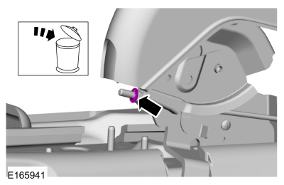 Loosen the parking brake cable adjustment nut.