Ford Fiesta: Manual Transmission - 6-Speed Manual Transmission – B6 / Manual Transmission - System Operation and Component Description. Description and Operation
System Operation
Neutral
- In NEUTRAL there is no powerflow through the transmission.
- The vehicle will stay stationary.
1st Gear
- The input shaft drives the output shaft.
- The 1st gear on the input shaft drives 1st gear on the output shaft.
- The 1st/2nd gear synchronizer is splined to the output shaft.
- When the 1-2 synchronizer sleeve is shifted to the right, 1st gear is locked to the output shaft.
- The output shaft pinion gear drives the differential ring gear.
- The power flows through the side and pinion gears to the halfshafts.
- The vehicle will move forward.
2nd Gear
- The input shaft drives the output shaft.
- The 2nd gear on the input shaft drives 2nd gear on the output shaft.
- The 1st/2nd gear synchronizer is splined to the output shaft.
- When the 1-2 synchronizer sleeve is shifted to the left, 2nd gear is locked to the output shaft.
- The output shaft drives the differential ring gear.
- The power flows through the side and pinion gears to the halfshafts.
- The vehicle will move forward.
3rd Gear
- The input shaft drives the output shaft.
- The 3rd gear on the input shaft drives 3rd gear on the output shaft.
- The 3rd/4th gear synchronizer is splined to the input shaft.
- When the 3-4 synchronizer sleeve is shifted to the right, 3rd gear is locked to the input shaft.
- The output shaft drives the differential ring gear.
- The power flows through the side and pinion gears to the halfshafts.
- The vehicle will move forward.
4th Gear
- The input shaft drives the output shaft.
- The 4th gear on the input shaft drives 4th gear on the output shaft.
- The 3rd/4th gear synchronizer is splined to the input shaft.
- When the 3-4 synchronizer sleeve is shifted to the left, 4th gear is locked to the input shaft.
- The output shaft drives the differential ring gear.
- The power flows through the side and pinion gears to the halfshafts.
- The vehicle will move forward.
5th Gear
- The input shaft drives the output shaft.
- The 5th gear on the input shaft drives 5th gear on the output shaft.
- The 5th/6th gear synchronizer is splined to the output shaft.
- When the 5th/6th gear synchronizer sleeve is shifted to the right, 5th gear is locked to the output shaft.
- The output shaft drives the differential ring gear.
- The power flows through the side and pinion gears to the halfshafts.
- The vehicle will move forward.
6th Gear
- The input shaft drives the output shaft.
- The 6th gear on the input shaft drives 6th gear on the output shaft.
- The 5th/6th gear synchronizer is splined to the input shaft.
- When the 5th/6th gear synchronizer sleeve is shifted to the left, 6th gear is locked to the output shaft.
- The output shaft drives the differential ring gear.
- The power flows through the side and pinion gears to the halfshafts.
- The vehicle will move forward.
Reverse
- The input shaft drives the reverse idler gear.
- The reverse gear on the reverse gear output shaft drives reverse gear on the output shaft
- The reverse gear synchronizer is splined to the output shaft.
- When the reverse gear synchronizer sleeve is shifted right, reverse gear is locked to the output shaft. The reverse gear output shaft gear drives reverse gear on the input shaft, in a reverse direction.
- The output shaft drives the differential ring gear.
- The power flows through the side and pinion gears to the halfshafts.
- The vehicle will move rearward.
Component Description
Selector Mechanism
The selector mechanism is the link between the transmission shift cables and the transmission. It is externally mounted on the transmission and is consists of levers and rods which control the shift forks inside the transmission. The shift and selector cables connect to levers on the outside. The selector mechanism is replaced as an assembly.
Input Shaft
The input shaft is the main shaft splined to the clutch disc and turns the gears in the transmission.
The gears on the input shaft mesh with the output shaft gears and provide torque from the engine to the differential. 1st and 2nd gears are fixed and 3rd-6th gears are free to spin on the input shaft.
The input shaft has one roller bearing and one ball bearing.
Output Shaft
The output shaft transfers torque to the ring gear, pinion gears, and differential.
The output shaft has a gear for each drive gear, including reverse. 1st and 2nd gears are free to spin and 3rd-6th gears are fixed on the output shaft. The synchronizers engage the gears locking them to the output shaft.
The output shaft has one roller bearing and one ball bearing.
Differential
The ends of the differential are supported on tapered roller differential bearings. The cups for these differential bearings are seated in the transmission case and the flywheel housing. Differential bearing preload is set using a selective differential bearing shim that is installed under the differential bearing cup in the transmission case.
The differential includes the differential side gears and the shaft mounted differential pinion gears. Direct contact between the gears and the differential case is prevented by the differential side gear thrust washers installed under the gears. The differential pinion shaft is held in position by a differential pinion shaft lock pin that extends through the end of the differential pinion shaft and the differential case.
Reverse Gear Output Shaft
The reverse gear output shaft is supported at one end in the clutch housing and at the other in the transmission case by ball bearings.
When the reverse gear shift fork moves the reverse gear synchronizer on the reverse gear output shaft, it engages the reverse drive gear to the output shaft and drives the differential ring gear through a separate final drive pinion.
When the reverse gear rotates on the reverse gear output shaft, it reverses the power flow to the output shaft.
To engage the reverse gear, the motion of the shift fork is transferred to the reverse gearshift lever through the shift gate. When the reverse gearshift selector arm moves its end of the shift fork, the opposite end slides the reverse gear into engagement with the input shaft and output shaft reverse gears.
Synchronizer
The synchronizers are designed to act as the torque carrying interfaces between each speed gear and corresponding output shaft.
Gear selection is made by sliding the synchronizer sleeve towards a speed gear. This causes the internal splines of the synchronizer sleeve to bridge a gap between the output hub and the external spline feature of the speed gear, thus transmitting speed and torque between the gear and output shaft. Synchronizers are small cone wet friction clutches mounted to the transmission output shaft. They are used to bring the rotation speed of the engaging speed gear in sync with the output shaft speed. After synchronous speed has been attained the final power flow connection is made possible and the synchronizer sleeve is permitted to pass by and engage the external spline teeth on the speed gear.
 Manual Transmission - Overview. Description and Operation
The B6 6-speed manual transmission is a fully synchronized transmission including reverse gear.
The 1st and 2nd gears are triple cone synchronized. The 3rd, 4th, 5th, 6th and reverse gears are single cone synchronized...
 Manual Transmission. Diagnosis and Testing
Inspection and Verification
NOTICE:
If transmission noise is reported, check the fluid level
first. Do not drive the vehicle if the fluid level is low or damage can
occur...
Other information:
Ford Fiesta 2014 - 2019 Service Manual: Air Conditioning (A/C) Clutch and Air Conditioning (A/C) Clutch Field Coil. Removal and Installation
Special Tool(s) / General Equipment 412-134Holding Tool, Compressor ClutchTKIT-2006U-F/FMTKIT-2006U-FLM/LMTKIT-2006U-ROW1TKIT-2006U-ROW2 Removal NOTE: Removal steps in this procedure may contain installation details. Remove the A/C compressor...
Ford Fiesta 2014 - 2019 Service Manual: Wheel and Tire. Disassembly and Assembly
Special Tool(s) / General Equipment Wooden Block DISASSEMBLY NOTICE: Failure to follow the instructions below may result in damage to the TPMS sensor. NOTICE: The TPMS sensor is mounted to the valve stem. Removal of the valve stem requires dismounting the tire from the wheel and removal of the TPMS sensor...
Categories
- Manuals Home
- Ford Fiesta Service Manual (2014 - 2019)
- Engine - 1.6L EcoBoost (132kW/180PS) – Sigma
- Engine Component View. Description and Operation
- Engine. Assembly
- Clutch - 6-Speed Manual Transmission – B6
- Engine Cooling - 1.6L EcoBoost (132kW/180PS) – Sigma
Brake Backing Plate. Removal and Installation
Removal
NOTE: Removal steps in this procedure may contain installation details.
Remove the brake shoes.Refer to: Brake Shoes (206-02 Drum Brake, Removal and Installation).
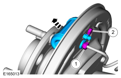
Disconnect the brake tube fitting.
Torque: 159 lb.in (18 Nm) Remove the bolt and wheel cylinder.
Torque: 106 lb.in (12 Nm)
 Disconnect the brake shoe lever fitting and re