Ford Fiesta: Handles, Locks, Latches and Entry Systems / Locks, Latches and Entry Systems. Diagnosis and Testing
DTC Chart: BCM
Diagnostics in this manual assume a certain skill level and knowledge of Ford-specific diagnostic practices.
REFER to: Diagnostic Methods (100-00 General Information, Description and Operation).
BCM
DTC Chart
|
DTC
|
Description
|
Action
|
|
B108F:23
|
Cabin Lock/Unlock Switch: Signal Stuck Low
|
GO to Pinpoint Test K
|
|
B1108:77
|
Driver Door Central Locking Motor: Commanded Position Not Reachable
|
GO to Pinpoint Test L
|
|
B1108:92
|
Driver Door Central Locking Motor: Performance or Incorrect Operation
|
GO to Pinpoint Test L
|
|
B113E:23
|
External Boot/Trunk Release Switch: Signal Stuck Low
|
GO to Pinpoint Test M
|
|
B1187:92
|
Trunk Motor: Performance or Incorrect Operation
|
GO to Pinpoint Test M
|
|
B1D21:62
|
Remote Control Switch: Signal Compare Failure
|
GO to Pinpoint Test N
|
|
All other Diagnostic Trouble Codes (DTCs)
|
-
|
REFER to: Body Control Module (BCM) (419-10 Multifunction Electronic Modules, Diagnosis and Testing).
|
DTC Chart: RFA Module
Diagnostics in this manual assume a certain skill level and knowledge of Ford-specific diagnostic practices.
REFER to: Diagnostic Methods (100-00 General Information, Description and Operation).
RFA Module DTC Chart
|
DTC
|
Description
|
Action
|
|
B10C6:1F
|
Exterior Trunk Antenna: Circuit Intermittent
|
GO to Pinpoint Test S
|
|
B10D1:24
|
Left Front Lock Button: Signal Stuck High
|
GO to Pinpoint Test R
|
|
B10D3:24
|
Right Front Lock Button: Signal Stuck High
|
GO to Pinpoint Test R
|
|
B113E:24
|
External Boot/Trunk: Signal Stuck High
|
GO to Pinpoint Test M
|
|
B11FD:1F
|
Left Front Exterior Antenna: Circuit Intermittent
|
GO to Pinpoint Test R
|
|
B1210:1F
|
Right Front Exterior Antenna: Circuit Intermittent
|
GO to Pinpoint Test R
|
|
U201F:00
|
External Receiver: No Sub Type Information
|
GO to Pinpoint Test O
|
|
U201F:13
|
External Receiver: Circuit Open
|
GO to Pinpoint Test O
|
|
All other Diagnostic Trouble Codes (DTCs)
|
-
|
REFER to: Remote Function Actuator (RFA) Module (419-10 Multifunction Electronic Modules, Removal and Installation).
|
Symptom Charts
Symptom Chart: Handles, Locks, Latches and Entry Systems - Mechanical
Diagnostics in this manual assume a certain skill level and knowledge of Ford-specific diagnostic practices.
REFER to: Diagnostic Methods (100-00 General Information, Description and Operation).
|
Condition
|
Possible Causes
|
Actions
|
|
Hard to open or close a door from either door handle
|
-
Refer to the Pinpoint Test
|
|
|
A door is difficult or does not open from the exterior door handle
|
-
Refer to the Pinpoint Test
|
|
|
A door is difficult or does not open from the interior door handle
|
-
Refer to the Pinpoint Test
|
|
|
The exterior door release handle sticks
|
-
Refer to the Pinpoint Test
|
|
|
The interior door release handle sticks
|
-
Refer to the Pinpoint Test
|
|
|
Squeak-rattle-chucking noise from door
|
-
Refer to the Pinpoint Test
|
|
|
The manual door lock cylinder is inoperative
|
-
Refer to the Pinpoint Test
|
|
|
The ignition lock cylinder difficult to turn
|
-
Refer to the Pinpoint Test
|
|
|
Key is hard to insert into the ignition lock cylinder
|
-
Refer to the Pinpoint Test
|
|
|
Ignition lock cylinder cannot be returned to OFF
|
-
Refer to the Pinpoint Test
|
-
REFER to: Steering Wheel and Column Electrical Components (211-05
Steering Wheel and Column Electrical Components, Diagnosis and Testing).
|
Symptom Chart: Handles, Locks, Latches and Entry Systems - Electrical
Diagnostics in this manual assume a certain skill level and knowledge of Ford-specific diagnostic practices.
REFER to: Diagnostic Methods (100-00 General Information, Description and Operation).
|
Condition
|
Possible Causes
|
Actions
|
|
All door locks are inoperative
|
-
Refer to the Pinpoint Test
|
|
|
A single or more than one door lock is inoperative
|
-
Refer to the Pinpoint Test
|
|
|
All door locks are inoperative from the door lock control switch
|
-
Refer to the Pinpoint Test
|
|
|
The door lock indicator is inoperative or always on
|
-
Refer to the Pinpoint Test
|
|
|
The liftgate/luggage compartment lid release is inoperative
|
-
Refer to the Pinpoint Test
|
|
|
The liftgate latch does not latch
|
-
Wiring, terminals or connectors
-
Liftgate latch
|
-
DISCONNECT the liftgate latch
electrical connector and CHECK the operation of the latch using a
screwdriver.
-
If the latch does not fully latch (2 clicks), INSTALL a new liftgate latch.
REFER to: Liftgate Latch (501-14 Handles, Locks, Latches and Entry Systems, Removal and Installation).
-
If the latch fully latches
(2 clicks), REFER to the Wiring Diagrams manual to identify the possible
causes of the circuit short.
|
|
The luggage compartment lid latch does not latch
|
-
Wiring, terminals or connectors
-
Luggage compartment lid latch
|
-
DISCONNECT the luggage
compartment lid latch electrical connector and CHECK the operation of
the latch using a screwdriver.
-
If the latch does not fully
latch (2 clicks), INSTALL a new luggage compartment lid latch.
REFER to: Luggage Compartment Lid Latch (501-14 Handles, Locks, Latches and Entry Systems, Removal and Installation).
-
If the latch fully latches
(2 clicks), REFER to the Wiring Diagrams manual to identify the possible
causes of the circuit short.
|
|
The RKE transmitter is inoperative (without push-button start)
|
-
Refer to the Pinpoint Test
|
|
|
The RKE transmitter is inoperative (with push-button start)
|
-
Refer to the Pinpoint Test
|
|
|
An individual button/feature is inoperative from the RKE transmitter
|
-
Refer to the Pinpoint Test
|
|
|
The RKE transmitter has poor range performance
|
-
Refer to the Pinpoint Test
|
|
|
The autolock is inoperative
|
|
-
ENABLE the autolock feature. REFER to the Owner's Literature.
|
|
The auto-unlock is inoperative
|
|
-
ENABLE the auto-unlock feature. REFER to the Owner's Literature.
|
|
The smart unlock is inoperative
|
-
Refer to the Pinpoint Test
|
-
For vehicles not equipped with
push-button start, DIAGNOSE the key-in-ignition warning chime.
REFER
to: Instrumentation, Message Center and Warning Chimes (413-01
Instrumentation, Message Center and Warning Chimes, Diagnosis and
Testing).
-
For vehicles equipped with
push-button start, DIAGNOSE the passive key not starting the vehicle
from various areas within the interior of the vehicle.
REFER to:
Passive Anti-Theft System (PATS) (419-01C Passive Anti-Theft System
(PATS) - Vehicles With: Keyless Entry and Push Button Start, Diagnosis
and Testing).
|
|
The liftgate/luggage compartment lid smart unlock is inoperative
|
-
Refer to the Pinpoint Test
|
-
DIAGNOSE the passive key not
starting the vehicle from various areas within the interior of the
vehicle.
REFER to: Passive Anti-Theft System (PATS) (419-01C Passive
Anti-Theft System (PATS) - Vehicles With: Keyless Entry and Push Button
Start, Diagnosis and Testing).
|
|
The 2-stage door unlocking does not operate correctly
|
-
The 2-stage door unlocking is not programmed correctly
|
-
PROGRAM the 2-stage door unlocking.
REFER to: Staged Unlock Programming (501-14 Handles, Locks, Latches and Entry Systems, General Procedures).
|
|
A door passive entry feature is inoperative
|
-
Refer to the Pinpoint Test
|
|
|
The liftgate/luggage compartment lid passive entry feature is inoperative
|
-
Refer to the Pinpoint Test
|
|
Pinpoint Tests
Hard To Open Or Close a Door From Either Door Handle
Normal Operations and Fault Conditions
The
door latch can be actuated from the interior or exterior door handle.
When actuated, the door latch releases and allows the door to open. If
the door latch or the door hinges have insufficient lubrication or if
the striker or door are misaligned, it causes extra force to be used
when opening or closing the door.
Possible Causes
-
Door alignment
-
Door hinges
-
Striker adjustment
-
Door latch
PINPOINT TEST A: HARD TO OPEN OR CLOSE A DOOR FROM EITHER DOOR HANDLE
| A1 CHECK THE LATCH OPERATION FROM BOTH DOOR HANDLES |
-
Open the door using both the interior and exterior door handles.
Does the door open normally from one of the door handles?
| Yes |
If the door is difficult to open from the exterior door handle, GO to Pinpoint Test B
If the door is difficult to open from the interior door handle, GO to Pinpoint Test C
|
|
| A2 CHECK THE LATCH OPERATION |
-
Using a screwdriver, fully close the latch (2 clicks).
-
Verify the latch releases easily while pulling on the interior/exterior door handle.
Does the latch release easily?
|
| A3 CHECK THE LATCH OPERATION AFTER LUBRICATION |
-
Lubricate the door latch.
REFER to: Door Latch Lubrication (501-14 Handles, Locks, Latches and Entry Systems, General Procedures).
-
Using a screwdriver, fully close the latch (2 clicks).
-
Verify the latch releases easily while pulling on the interior/exterior door handle.
Does the latch release easily?
| Yes |
The concern was caused by an insufficiently lubricated door latch.
|
| No |
INSTALL a new door latch. For a front door latch,
REFER to: Front Door Latch (501-14 Handles, Locks, Latches and Entry Systems, Removal and Installation). For a rear door latch,
REFER to: Rear Door Latch (501-14 Handles, Locks, Latches and Entry Systems, Removal and Installation).
|
|
| A4 CHECK THE STRIKER ADJUSTMENT |
-
Check the adjustment of the striker.
Is the striker adjusted correctly?
| No |
ADJUST the striker as necessary.
|
|
| A5 CHECK THE DOOR ALIGNMENT |
-
Check the alignment of the door.
Is the door aligned correctly?
| Yes |
LUBRICATE the door hinges.
|
| No |
ADJUST the door as necessary. For a front door,
REFER to: Front Door Alignment (501-03 Body Closures, General Procedures). For a rear door,
REFER to: Rear Door Alignment (501-03 Body Closures, General Procedures).
|
|
A Door Is Difficult Or Does Not Open From The Exterior Door Handle
Normal Operations and Fault Conditions
The
exterior door handle is connected to the door latch with an actuating
cable. When the exterior door handle is pulled, the actuating cable
pulls on the latch lever. When the latch lever moves, the door latch
releases, allowing the door to open.
Possible Causes
-
Broken or binding linkage
-
Exterior door handle reinforcement
-
Door latch
PINPOINT TEST B: A DOOR IS DIFFICULT OR DOES NOT OPEN FROM THE EXTERIOR DOOR HANDLE
| B1 CHECK THE LATCH OPERATION FROM BOTH DOOR HANDLES |
-
NOTE:
The rear door interior door handle has to be pulled twice to unlock and unlatch.
Open and close the door using both the interior and exterior door handles.
Does the door open normally from one of the door handles?
| Yes |
If the door is difficult/does not open from only the exterior door handle, GO to B2
If the door is difficult/does not open from only the interior door handle, GO to Pinpoint Test C
|
|
| B2 CHECK THE EXTERIOR DOOR HANDLE AND CABLE OPERATION |
-
Disconnect the exterior door handle actuating cable from the door latch.
-
Operate the exterior door handle while observing the linkage and cable.
Are any of the exterior door handle components or linkages binding or broken?
| No |
INSTALL a new door latch. For a front door,
REFER to: Front Door Latch (501-14 Handles, Locks, Latches and Entry Systems, Removal and Installation). For a rear door,
REFER to: Rear Door Latch (501-14 Handles, Locks, Latches and Entry Systems, Removal and Installation).
|
|
| B3 CHECK THE EXTERIOR DOOR HANDLE REINFORCEMENT |
-
Disconnect the exterior door handle actuating cable from the exterior door handle reinforcement.
-
Pull and release the exterior door handle.
Does the exterior door handle operate correctly?
| Yes |
INSTALL a new exterior door handle cable.
|
| No |
INSTALL a new exterior door handle reinforcement. For a front door,
REFER
to: Exterior Front Door Handle Reinforcement (501-14 Handles, Locks,
Latches and Entry Systems, Removal and Installation). For a rear door,
REFER to: Exterior Rear Door Handle Reinforcement (501-14 Handles, Locks, Latches and Entry Systems, Removal and Installation).
|
|
A Door Is Difficult Or Does Not Open From The Interior Door Handle
Normal Operations and Fault Conditions
The
interior door handle is connected to the door latch by an actuating
cable. When the interior door handle is pulled, the cable pulls on the
latch lever. When the latch lever moves, the door latch releases,
allowing the door to open.
Possible Causes
-
Broken or binding cable/linkage
-
Door latch
Visual Inspection and Diagnostic Pre-checks
-
For the rear doors, make sure the child safety lock is in the unlock position.
PINPOINT TEST C: A DOOR IS DIFFICULT OR DOES NOT OPEN FROM THE INTERIOR DOOR HANDLE
| C1 CHECK THE LATCH OPERATION FROM BOTH DOOR HANDLES |
|
NOTE:
Make sure the child safety lock is in the unlock position for the rear doors.
-
NOTE:
The rear door interior door handle must be pulled twice to unlock and unlatch.
Open the door using both the interior and exterior door handles.
Does the door open normally from one of the door handles?
| Yes |
If the door is difficult/does not open from only the interior door handle, GO to C2
If the door is difficult/does not open from only the exterior door handle, GO to Pinpoint Test B
|
|
| C2 CHECK THE INTERIOR DOOR HANDLE AND CABLE/LINKAGE OPERATION |
-
Remove the door trim panel.
-
Install the interior door handle back onto the release cable.
-
Operate the interior door handle while observing the cable/linkage.
Are any of the interior door handle components or cable/linkages binding or broken?
| No |
INSTALL a new door latch. For a front door,
REFER to: Front Door Latch (501-14 Handles, Locks, Latches and Entry Systems, Removal and Installation). For a rear door,
REFER to: Rear Door Latch (501-14 Handles, Locks, Latches and Entry Systems, Removal and Installation).
|
|
The Exterior Door Release Handle Sticks
Normal Operations and Fault Conditions
The
exterior door handle is connected to the door latch with an actuating
cable. When the exterior door handle is pulled, the actuating cable
pulls on the latch lever. When the latch lever moves, the door latch
releases, allowing the door to open. The handle has a return spring to
make sure the handle returns to a closed position.
Possible Causes
-
Binding linkage
-
Broken handle return spring
-
Door latch
PINPOINT TEST D: THE EXTERIOR DOOR RELEASE HANDLE STICKS
| D1 CHECK THE EXTERIOR DOOR HANDLE AND LINKAGE OPERATION |
-
Disconnect the exterior door handle actuating cable from the door latch.
-
Operate the exterior door handle while observing the linkage.
Are any of the exterior door handle components or linkages binding?
| No |
INSTALL a new door latch. For a front door,
REFER to: Front Door Latch (501-14 Handles, Locks, Latches and Entry Systems, Removal and Installation). For a rear door,
REFER to: Rear Door Latch (501-14 Handles, Locks, Latches and Entry Systems, Removal and Installation).
|
|
| D2 CHECK FOR A BROKEN RETURN SPRING |
-
Disconnect the exterior door handle actuating cable from the exterior door handle reinforcement.
-
Pull and release the exterior door handle.
Does the exterior door handle return to a closed position once released?
| Yes |
INSTALL a new exterior door handle cable.
|
| No |
INSTALL a new exterior door handle reinforcement. For a front door,
REFER
to: Exterior Front Door Handle Reinforcement (501-14 Handles, Locks,
Latches and Entry Systems, Removal and Installation). For a rear door,
REFER to: Exterior Rear Door Handle Reinforcement (501-14 Handles, Locks, Latches and Entry Systems, Removal and Installation).
|
|
The Interior Door Release Handle Sticks
Normal Operations and Fault Conditions
The
interior door handle is connected to the door latch by an actuating
cable. When the interior door handle is pulled, the cable pulls on the
latch lever. When the latch lever is moved, the door latch releases,
allowing the door to open. The handle has a return spring to make sure
the handle returns to a closed position.
Possible Causes
-
Binding cable
-
Broken handle return spring
-
Door latch
PINPOINT TEST E: THE INTERIOR DOOR RELEASE HANDLE STICKS
| E1 CHECK FOR A BROKEN RETURN SPRING |
-
Remove the interior door handle.
-
For a front door,
REFER to: Interior Front Door Handle (501-14 Handles, Locks, Latches and Entry Systems, Removal and Installation).
-
For a rear door,
REFER to: Interior Rear Door Handle (501-14 Handles, Locks, Latches and Entry Systems, Removal and Installation).
-
Pull and release the interior door handle.
Does the interior door handle return to a closed position once released?
| No |
INSTALL a new interior door handle. For a front door,
REFER to:
Interior Front Door Handle (501-14 Handles, Locks, Latches and Entry
Systems, Removal and Installation). For a rear door,
REFER to: Interior Rear Door Handle (501-14 Handles, Locks, Latches and Entry Systems, Removal and Installation).
|
|
| E2 CHECK THE INTERIOR DOOR HANDLE CABLE OPERATION |
-
Remove the interior door latch release cable.
-
Observe the door latch release cable for any damage or binding.
Is the door latch release cable OK?
| Yes |
INSTALL a new door latch. For a front door,
REFER to: Front Door Latch (501-14 Handles, Locks, Latches and Entry Systems, Removal and Installation). For a rear door,
REFER to: Rear Door Latch (501-14 Handles, Locks, Latches and Entry Systems, Removal and Installation).
|
| No |
INSTALL a new interior door handle cable.
|
|
Squeak-Rattle-Chucking Noise From Door
Possible Causes
-
Door alignment
-
Striker adjustment
-
Door latch
PINPOINT TEST F: SQUEAK-RATTLE-CHUCKING NOISE FROM DOOR
| F1 CHECK FOR ANY LOOSE COMPONENTS |
-
Remove the door trim panel.
-
For a front door,
REFER to: Front Door Trim Panel (501-05 Interior Trim and Ornamentation, Removal and Installation).
-
For a rear door,
REFER to: Rear Door Trim Panel (501-05 Interior Trim and Ornamentation, Removal and Installation).
-
Inspect inside the door for any loose components.
Are there any loose components inside the door?
|
| F2 CHECK THE STRIKER ADJUSTMENT |
-
Check the adjustment of the striker.
Is the striker adjusted correctly?
| No |
ADJUST the striker as necessary.
|
|
| F3 CHECK THE DOOR ALIGNMENT |
-
Check the alignment of the door.
Is the door aligned correctly?
| No |
ADJUST the door as necessary. For a front door,
REFER to: Front Door Alignment (501-03 Body Closures, General Procedures). For a rear door,
REFER to: Rear Door Alignment (501-03 Body Closures, General Procedures).
|
|
| F4 CHECK THE LATCH OPERATION AFTER LUBRICATION |
-
Lubricate the door latch.
REFER to: Door Latch Lubrication (501-14 Handles, Locks, Latches and Entry Systems, General Procedures).
-
Using a screwdriver, fully close the latch (2 clicks).
-
Operate the door latch and listen for the noise.
Is the original noise still present after the latch is lubricated?
| Yes |
INSTALL a new door latch. For a front door,
REFER to: Front Door Latch (501-14 Handles, Locks, Latches and Entry Systems, Removal and Installation). For a rear door,
REFER to: Rear Door Latch (501-14 Handles, Locks, Latches and Entry Systems, Removal and Installation).
|
| No |
The concern was caused by an insufficiently lubricated door latch.
|
|
The Manual Door Lock Cylinder Inoperative
Normal Operations and Fault Conditions
The door lock cylinder is connected to the door latch via a lock rod and can be used to manually lock/unlock the door.
Possible Causes
-
Bent or binding lock rod and lever
-
Door lock cylinder
-
Door latch
PINPOINT TEST G: THE MANUAL DOOR LOCK CYLINDER INOPERATIVE
| G1 CHECK THE LOCK AND UNLOCK OPERATION |
-
Insert a key into the lock cylinder and rotate the lock cylinder to the lock and unlock positions.
Does the door lock cylinder freely rotate without locking and unlocking the door?
|
| G2 CHECK THE DOOR LOCK CYLINDER (FREE-SPIN) |
-
Remove the door lock cylinder.
REFER to: Front Door Lock Cylinder (501-14 Handles, Locks, Latches and Entry Systems, Removal and Installation).
-
Operate the door lock cylinder with the key while holding the lever on the lock cylinder.
Does the key in the door lock cylinder rotate freely while the lever is stationary?
| Yes |
INSTALL a new door lock cylinder.
REFER to: Front Door Lock Cylinder (501-14 Handles, Locks, Latches and Entry Systems, Removal and Installation).
|
|
| G3 CHECK THE DOOR LOCK CYLINDER LINKAGE CONNECTION |
-
Inspect the door lock cylinder linkage.
Is the door lock cylinder rod and lever disconnected?
| Yes |
CONNECT the door lock cylinder rod and lever.
|
| No |
INSTALL a new door latch.
REFER to: Front Door Latch (501-14 Handles, Locks, Latches and Entry Systems, Removal and Installation).
|
|
| G4 CHECK THE LOCK CYLINDER OPERATION AFTER LUBRICATION |
-
Spray a lock lubricant (such as Motorcraft® XL-1) into the lock cylinder opening for a couple of seconds.
-
Operate the door lock cylinder with the key.
Does the door lock and unlock using the door lock cylinder?
| Yes |
The concern was caused by an insufficiently
lubricated lock cylinder. SPRAY a multi-purpose grease (such as
Motorcraft® XL-5) into the lock cylinder for a couple seconds to provide
long term lubrication.
|
|
| G5 CHECK THE DOOR LOCK CYLINDER FOR BINDING |
-
Remove the door lock cylinder.
REFER to: Front Door Lock Cylinder (501-14 Handles, Locks, Latches and Entry Systems, Removal and Installation).
-
Operate the door lock cylinder with the key.
Does the door lock cylinder rotate freely?
| No |
INSTALL a new door lock cylinder.
REFER to: Front Door Lock Cylinder (501-14 Handles, Locks, Latches and Entry Systems, Removal and Installation).
|
|
| G6 CHECK THE DOOR LOCK CYLINDER LINKAGE |
-
Operate the door lock using the door lock cylinder linkage.
-
Operate the door lock cylinder with the key.
Is the door lock cylinder rod and lever binding, damaged or disconnected?
| No |
INSTALL a new door latch.
REFER to: Front Door Latch (501-14 Handles, Locks, Latches and Entry Systems, Removal and Installation).
|
|
The Ignition Lock Cylinder Difficult To Turn
Normal Operations and Fault Conditions
The
ignition lock cylinder mechanically rotates the ignition switch within
the ignition lock cylinder housing. Insertion and extraction of the key
and rotation of the lock cylinder using a correctly cut key should be
smooth and require minimal effort.
Possible Causes
-
Key
-
Ignition switch
-
Ignition lock cylinder
PINPOINT TEST H: THE IGNITION LOCK CYLINDER DIFFICULT TO TURN
| H1 CHECK THE KEY BLADE FOR DAMAGE |
-
Inspect the key for an incorrect cut, burrs or damage.
Is the key correctly cut and free of burrs and damage?
| No |
REPLACE and PROGRAM a new key.
REFER to: Key Programming Using
Diagnostic Equipment (419-01B Passive Anti-Theft System (PATS) -
Vehicles Without: Keyless Entry and Push Button Start, General
Procedures). If the replacement key is equipped with a RKE transmitter,
PROGRAM the RKE transmitter.
REFER to: Remote Keyless Entry (RKE)
Transmitter Programming (501-14 Handles, Locks, Latches and Entry
Systems, General Procedures).
|
|
| H2 CHECK THE IGNITION LOCK CYLINDER OPERATION |
-
Insert the key into the ignition lock cylinder and rotate the key through all ignition switch positions.
Does the key rotate through all ignition switch positions without excessive effort?
| Yes |
The mechanical function of the ignition lock cylinder is OK.
|
|
| H3 CHECK THE IGNITION LOCK CYLINDER WHILE INSERTING THE KEY |
-
Remove the ignition lock cylinder.
REFER to: Ignition Lock Cylinder (501-14 Handles, Locks, Latches and Entry Systems, Removal and Installation).
-
While holding the ignition lock cylinder, apply finger pressure to the back of the lock.
-
With pressure still applied to the back of the lock,
insert and remove the key from the ignition lock cylinder. Repeat this
step several times.
Does the key insert and remove freely into the ignition lock cylinder?
| No |
INSTALL a new ignition lock cylinder.
REFER to: Ignition Lock Cylinder (501-14 Handles, Locks, Latches and Entry Systems, Removal and Installation).
|
|
| H4 CHECK THE IGNITION LOCK CYLINDER FOR BINDING ROTATION |
-
While holding the ignition lock cylinder, apply finger pressure to the back of the lock.
-
With pressure still applied to the back of the lock,
use the key to rotate the ignition lock cylinder through all positions.
Does the ignition lock cylinder rotate freely?
| Yes |
INSTALL a new ignition switch.
REFER to: Ignition Switch - Vehicles
Without: Keyless Entry and Push Button Start (211-05 Steering Wheel and
Column Electrical Components, Removal and Installation).
|
| No |
INSTALL a new ignition lock cylinder.
REFER to: Ignition Lock Cylinder (501-14 Handles, Locks, Latches and Entry Systems, Removal and Installation).
|
|
All Door Locks Are Inoperative
Refer to Wiring Diagrams Cell 117 for schematic and connector information.
Normal Operations and Fault Conditions
REFER to: Handles, Locks, Latches and Entry Systems - System
Operation and Component Description (501-14 Handles, Locks, Latches and
Entry Systems, Description and Operation).
Possible Causes
-
Fuse
-
Wiring, terminals or connectors
-
Liftgate/luggage compartment lid/ latch
-
BCM
PINPOINT TEST I: ALL DOOR LOCKS ARE INOPERATIVE
| I1 VERIFY THE DOOR LOCK OPERATION FROM THE RKE (REMOTE KEYLESS ENTRY)
TRANSMITTER AND THE DOOR LOCK CONTROL SWITCH |
-
Press the LOCK and UNLOCK buttons on a RKE transmitter and press the interior door lock control switch.
Are the door locks inoperative from the RKE transmitter and door lock control switch?
| Yes |
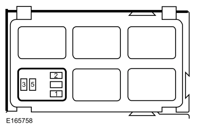
VERIFY the BJB fuse 4 (20A) is OK. If OK, GO to I2
If not OK, GO to I5
|
| No |
If the door locks are inoperative from the door lock control switch, GO to Pinpoint Test K
If the door locks are inoperative from the RKE transmitter (vehicles without push-button start), GO to Pinpoint Test N
If the door locks are inoperative from the RKE transmitter (vehicles with push-button start), GO to Pinpoint Test O
|
|
| I2 CHECK THE BCM (BODY CONTROL MODULE)
POWER DOOR LOCK VOLTAGE SUPPLY CIRCUIT FOR AN OPEN |
-
Measure:
Click to display connectors
|
Positive Lead
|
Measurement / Action
|
Negative Lead
|
|
C2280C-16
|

|
Ground
|
the voltage greater than 11 volts?
|
| I3 CHECK THE BCM (BODY CONTROL MODULE)
POWER DOOR LOCK GROUND CIRCUIT FOR AN OPEN |
-
Measure:
Click to display connectors
|
Positive Lead
|
Measurement / Action
|
Negative Lead
|
|
C2280B-16
|

|
Ground
|
Is the resistance less than 3 ohms?
|
| I4 CHECK THE LOCK CIRCUIT FOR AN OPEN |
-
Disconnect Right Front Door Latch C609
.
-
Measure
Click to display connectors
|
Positive Lead
|
Measurement / Action
|
Negative Lead
|
|
C2280C-3
|
|
C609-2
|
Is the resistance less than 3 ohms?
|
| I5 CHECK THE BCM (BODY CONTROL MODULE)
LIFTGATE/LUGGAGE COMPARTMENT LID RELEASE OUTPUT FOR A SHORT TO GROUND |
|
NOTE:
If BJB fuse 6 (30A) fails immediately upon installation, repair the BCM
power door lock voltage supply circuit for a short to ground.
-
Install a new BJB fuse 4 (20A).
-
Operate the liftgate/luggage compartment lid release
by pressing the liftgate/luggage compartment lid release button on a RKE transmitter.
Is the BJB fuse 4 (20A) OK?
|
| I6 ISOLATE THE BCM (BODY CONTROL MODULE)
LIFTGATE/LUGGAGE COMPARTMENT LID RELEASE OUTPUT CIRCUIT FOR A SHORT TO GROUND |
-
Disconnect Liftgate/Luggage Compartment Lid Latch C4223
.
-
Install a new BJB fuse 4 (20A).
-
Operate the liftgate/luggage compartment lid release
by pressing the liftgate/luggage compartment lid release button on a RKE transmitter.
Is the BJB fuse 4 (20A) OK?
| Yes |
For 4-door vehicles, INSTALL a new luggage compartment lid latch.
REFER to: Luggage Compartment Lid Latch (501-14 Handles, Locks, Latches and Entry Systems, Removal and Installation).
For 5-door vehicles, INSTALL a new liftgate latch.
REFER to: Liftgate Latch (501-14 Handles, Locks, Latches and Entry Systems, Removal and Installation).
|
|
| I7 CHECK THE LOCK CIRCUIT FOR A SHORT TO GROUND |
-
Operate the door lock actuators by pressing the lock button on a RKE transmitter.
Is the BJB fuse 4 (20A) OK?
| Yes |
REPAIR the BCM unlock output circuit for a short to ground.
|
| No |
REPAIR the BCM lock output circuit for a short to ground.
|
|
| I8 CHECK FOR CORRECT BCM (BODY CONTROL MODULE)
OPERATION |
-
Disconnect and inspect all the BCM connectors.
-
Repair:
-
corrosion (install new connectors or terminals - clean module pins)
-
damaged or bent pins - install new terminals pins
-
pushed-out pins - install new pins as necessary
-
Reconnect the BCM connectors and make sure they seat and latch correctly.
-
Operate the system and determine if the concern is still present.
Is the concern still present?
| Yes |
CHECK OASIS for any applicable Technical Service Bulletins (TSBs). If a
TSB exists for this concern, DISCONTINUE this test and FOLLOW TSB
instructions. If no Technical Service Bulletins (TSBs) address this
concern, INSTALL a new BCM .
REFER to: Body Control Module (BCM) (419-10 Multifunction Electronic Modules, Removal and Installation).
|
| No |
The system is operating correctly at this time. The
concern may have been caused by module connections. ADDRESS the root
cause of any connector or pin issues.
|
|
A Single or More Than One Door Lock Is Inoperative
Refer to Wiring Diagrams Cell 117 for schematic and connector information.
Normal Operations and Fault Conditions
REFER to: Handles, Locks, Latches and Entry Systems - System
Operation and Component Description (501-14 Handles, Locks, Latches and
Entry Systems, Description and Operation).
Possible Causes
-
Wiring, terminals or connectors
-
Door latch
-
BCM
PINPOINT TEST J: A SINGLE OR MORE THAN ONE DOOR LOCK IS INOPERATIVE
| NOTICE:
The following Pinpoint Test uses a test light to
simulate normal circuit loads. Use only a Rotunda Test Lamp (SGT27000)
or 250-300mA incandescent bulb test lamp. To avoid connector terminal
damage, use the Rotunda Flex Probe kit for the test lamp probe
connection to the vehicle. Do not use the test lamp probe directly on
any connector.
|
| J1 CHECK THE LOCK OUTPUT CIRCUIT FOR AN OPEN |
-
Disconnect suspect door latch.
-
For the suspect door latch, connect:
Click to display connectors
Left Front Door Latch
|
Lead 1
|
Measurement / Action
|
Lead 2
|
|
C525-7
|

|
Ground
|
Click to display connectors
Right Front Door Latch
|
Lead 1
|
Measurement / Action
|
Lead 2
|
|
C609-2
|
|
Ground
|
Click to display connectors
Left Rear Door Latch
|
Lead 1
|
Measurement / Action
|
Lead 2
|
|
C705-7
|
|
Ground
|
Click to display connectors
Right Rear Door Latch
|
Lead 1
|
Measurement / Action
|
Lead 2
|
|
C805-2
|
|
Ground
|
-
NOTE:
The BCM only supplies voltage to the actuator momentarily. It is
important to monitor the test lamp while pressing the lock button.
Observe the test lamp while pressing the lock button on a RKE
transmitter.
Does the test lamp momentarily illuminate?
|
| J2 CHECK THE UNLOCK OUTPUT CIRCUIT FOR AN OPEN |
-
For the suspect door latch, connect:
Click to display connectors
Left Front Door Latch
|
Lead 1
|
Measurement / Action
|
Lead 2
|
|
C525-8
|
|
Ground
|
Click to display connectors
Right Front Door Latch
|
Lead 1
|
Measurement / Action
|
Lead 2
|
|
C609-1
|
|
Ground
|
Click to display connectors
Left Rear Door Latch
|
Lead 1
|
Measurement / Action
|
Lead 2
|
|
C705-8
|
|
Ground
|
Click to display connectors
Right Rear Door Latch
|
Lead 1
|
Measurement / Action
|
Lead 2
|
|
C805-1
|
|
Ground
|
-
NOTE:
The BCM only supplies voltage to the actuator momentarily. It is
important to monitor the test lamp while pressing the unlock button.
Observe the test lamp while pressing the unlock button on a RKE
transmitter.
Does the test lamp momentarily illuminate?
| Yes |
INSTALL a new door latch. For a front door,
REFER to: Front Door Latch (501-14 Handles, Locks, Latches and Entry Systems, Removal and Installation). For a rear door,
REFER to: Rear Door Latch (501-14 Handles, Locks, Latches and Entry Systems, Removal and Installation).
|
|
| J3 CHECK THE BCM (BODY CONTROL MODULE)
UNLOCK OUTPUT CIRCUIT FOR AN OPEN |
-
For the suspect door latch, measure:
Click to display connectors
Left Front Door Latch
|
Positive Lead
|
Measurement / Action
|
Negative Lead
|
|
C525-8
|
|
C2280C-8
|
Click to display connectors
Right Front Door Latch
|
Positive Lead
|
Measurement / Action
|
Negative Lead
|
|
C609-1
|
|
C2280C-2
|
Click to display connectors
Left Rear Door Latch
|
Positive Lead
|
Measurement / Action
|
Negative Lead
|
|
C705-8
|
|
C2280C-2
|
Click to display connectors
Right Rear Door Latch
|
Positive Lead
|
Measurement / Action
|
Negative Lead
|
|
C805-1
|
|
C2280C-2
|
Is the resistance less than 3 ohms?
|
| J4 CHECK FOR CORRECT BCM (BODY CONTROL MODULE)
OPERATION |
-
Disconnect and inspect all the BCM connectors.
-
Repair:
-
corrosion (install new connectors or terminals - clean module pins)
-
damaged or bent pins - install new terminals pins
-
pushed-out pins - install new pins as necessary
-
Reconnect the BCM connectors and make sure they seat and latch correctly.
-
Operate the system and determine if the concern is still present.
Is the concern still present?
| Yes |
CHECK OASIS for any applicable Technical Service Bulletins (TSBs). If a
TSB exists for this concern, DISCONTINUE this test and FOLLOW TSB
instructions. If no Technical Service Bulletins (TSBs) address this
concern, INSTALL a new BCM .
REFER to: Body Control Module (BCM) (419-10 Multifunction Electronic Modules, Removal and Installation).
|
| No |
The system is operating correctly at this time. The
concern may have been caused by module connections. ADDRESS the root
cause of any connector or pin issues.
|
|
All Door Locks Are Inoperative From The Door Lock Control Switch
Refer to Wiring Diagrams Cell 117 for schematic and connector information.
Normal Operations and Fault Conditions
REFER to: Handles, Locks, Latches and Entry Systems - System
Operation and Component Description (501-14 Handles, Locks, Latches and
Entry Systems, Description and Operation).
BCM
DTC Fault Trigger Conditions
|
DTC
|
Description
|
Fault Trigger Conditions
|
|
B108F:23
|
Cabin Lock/Unlock Switch: Signal Stuck Low
|
Sets when the BCM detects a short to ground from the door lock control switch input circuit.
|
Possible Causes
-
Wiring, terminals or connectors
-
FCIM
-
BCM
PINPOINT TEST K: ALL DOOR LOCKS ARE INOPERATIVE FROM THE DOOR LOCK CONTROL SWITCH
| K1 CHECK FOR BCM (BODY CONTROL MODULE)
DTC (DIAGNOSTIC TROUBLE CODE)
B108F:23 |
-
Using a diagnostic scan tool, perform the BCM self-test.
Is DTC B108F:23 present?
|
| K2 ISOLATE THE FCIM (FRONT CONTROLS INTERFACE MODULE)
FOR A SHORT TO GROUND |
-
Using a diagnostic scan tool, clear the BCM Diagnostic Trouble Codes (DTCs).
-
Using a diagnostic scan tool, perform the BCM self-test.
Is DTC B108F:23 still present?
| No |
INSTALL a new FCIM . REFER to Section 415-00.
|
|
| K3 CHECK THE DOOR LOCK CONTROL SWITCH INPUT CIRCUIT FOR A SHORT TO GROUND |
-
Measure:
Click to display connectors
|
Positive Lead
|
Measurement / Action
|
Negative Lead
|
|
C2280F-20
|
|
Ground
|
Is the resistance greater than 10,000 ohms?
|
| K4 BYPASS THE FCIM (FRONT CONTROLS INTERFACE MODULE)
|
-
Momentarily connect:
Click to display connectors
|
Lead 1
|
Measurement / Action
|
Lead 2
|
|
C2402-6
|

|
C2402-5
|
Do the doors lock/unlock when the jumper wire is connected?
| Yes |
INSTALL a new FCIM . REFER to Section 415-00.
|
|
| K5 CHECK THE FCIM (FRONT CONTROLS INTERFACE MODULE)
GROUND CIRCUIT FOR AN OPEN |
-
Measure:
Click to display connectors
|
Positive Lead
|
Measurement / Action
|
Negative Lead
|
|
C2402-5
|
|
Ground
|
Is the resistance less than 3 ohms?
|
| K6 CHECK THE DOOR LOCK CONTROL SWITCH INPUT CIRCUIT FOR AN OPEN |
-
Measure:
Click to display connectors
|
Positive Lead
|
Measurement / Action
|
Negative Lead
|
|
C2402-6
|
|
C2280F-20
|
Is the resistance less than 3 ohms?
|
| K7 CHECK FOR CORRECT BCM (BODY CONTROL MODULE)
OPERATION |
-
Disconnect and inspect all the BCM connectors.
-
Repair:
-
corrosion (install new connectors or terminals - clean module pins)
-
damaged or bent pins - install new terminals pins
-
pushed-out pins - install new pins as necessary
-
Reconnect the BCM connectors and make sure they seat and latch correctly.
-
Operate the system and determine if the concern is still present.
Is the concern still present?
| Yes |
CHECK OASIS for any applicable Technical Service Bulletins (TSBs). If a
TSB exists for this concern, DISCONTINUE this test and FOLLOW TSB
instructions. If no Technical Service Bulletins (TSBs) address this
concern, INSTALL a new BCM .
REFER to: Body Control Module (BCM) (419-10 Multifunction Electronic Modules, Removal and Installation).
|
| No |
The system is operating correctly at this time. The
concern may have been caused by module connections. ADDRESS the root
cause of any connector or pin issues.
|
|
The Door Lock Indicator Is Inoperative Or Always On
Refer to Wiring Diagrams Cell 117 for schematic and connector information.
Normal Operations and Fault Conditions
REFER to: Handles, Locks, Latches and Entry Systems - System
Operation and Component Description (501-14 Handles, Locks, Latches and
Entry Systems, Description and Operation).
BCM
DTC Fault Trigger Conditions
|
DTC
|
Description
|
Fault Trigger Conditions
|
|
B1108:77
|
Driver Door Central Locking Motor: Commanded Position Not Reachable
|
Sets continuous when the BCM detects the incorrect feedback on the door
lock/unlock monitor circuit after a central lock or unleck event. When
the BCM commands the doors to lock, it expects the lock/unlock monitor
circuit to be open. When the BCM commands all the doors to unlock, it
expects the lock/unlock monitor circuit to be grounded.
|
|
B1108:92
|
Driver Door Central Locking Motor: Performance or Incorrect Operation
|
Sets only during the BCM self-test when it detects the incorrect
feedback on the door lock/unlock monitor circuit. The BCM energizes the
internal lock and unlock relays to lock and unlock all of the doors.
When the BCM commands the doors to lock, it expects the lock/unlock
monitor circuit to be open. When the BCM commands the doors to unlock,
it expects the lock/unlock monitor circuit to be grounded.
|
Possible Causes
-
Wiring, terminals or connectors
-
Door latch
-
FCIM
-
BCM
PINPOINT TEST L: THE DOOR LOCK INDICATOR IS INOPERATIVE OR ALWAYS ON
| L1 CHECK THE DOOR LOCK ACTUATOR OPERATION |
-
Check the operation of the door locks using the interior door lock control switch.
Do the door locks operate correctly?
| No |
IDENTIFY the symptom and REFER to the Symptom Chart:
Handles, Locks, Latches and Entry Systems in this section.
|
|
| L2 CHECK THE COURTESY LAMP OPERATION |
-
Open and then close each door, one at a time, while observing the operation of the courtesy lamps.
Do the courtesy lamps operate correctly?
| No |
REFER to: Interior Lighting (417-02 Interior Lighting, Diagnosis and Testing).
|
|
| L3 CHECK THE DOOR LOCK INDICATOR OPERATION WITH THE DOORS UNLOCKED |
|
NOTE:
Make sure the child safety lock is off before performing this pinpoint test.
-
Unlock the doors using a RKE transmitter.
Is the door lock indicator illuminated?
|
| L4 CHECK FOR BCM (BODY CONTROL MODULE)
DTC (DIAGNOSTIC TROUBLE CODE)
B1108:77 OR B1108:92 (INDICATOR ALWAYS ON) |
-
Using a diagnostic scan tool, perform the BCM self-test.
Is DTC B1108:77 or B1108:92 present?
|
| L5 CHECK THE UNLOCK FEEDBACK CIRCUIT FOR AN OPEN |
-
Using a RKE transmitter, unlock the doors.
-
Measure:
Click to display connectors
|
Positive Lead
|
Measurement / Action
|
Negative Lead
|
|
C2280G-8
|
|
Ground
|
Is the resistance less than 3 ohms?
|
| L6 CHECK THE BCM (BODY CONTROL MODULE)
DOOR LOCK INDICATOR OUTPUT |
-
Using a RKE transmitter, unlock the doors.
-
Measure:
Click to display connectors
|
Positive Lead
|
Measurement / Action
|
Negative Lead
|
|
C2402-2
|
|
Ground
|
Is any voltage present?
| No |
INSTALL a new FCIM . REFER to Section 415-00.
|
|
| L7 CHECK THE BCM (BODY CONTROL MODULE)
DOOR LOCK INDICATOR OUTPUT FOR A SHORT TO VOLTAGE |
-
Measure:
Click to display connectors
|
Positive Lead
|
Measurement / Action
|
Negative Lead
|
|
C2402-2
|
|
Ground
|
Is any voltage present?
|
| L8 CHECK THE DOOR LOCK INDICATOR OPERATION WITH THE DOORS LOCKED |
-
Lock the doors using a RKE transmitter.
Is the door lock indicator illuminated?
|
| L9 CHECK FOR BCM (BODY CONTROL MODULE)
DTC (DIAGNOSTIC TROUBLE CODE)
B1108:77 OR B1108:92 (INDICATOR INOPERATIVE) |
-
Using a diagnostic scan tool, perform the BCM self-test.
Is DTC B1108:77 or B1108:92 present?
|
| L10 CHECK FOR VOLTAGE TO THE FCIM (FRONT CONTROLS INTERFACE MODULE)
|
-
Using a RKE transmitter, lock the doors.
-
Measure:
Click to display connectors
|
Positive Lead
|
Measurement / Action
|
Negative Lead
|
|
C2402-2
|
|
Ground
|
Is the voltage greater than 11 volts?
| Yes |
INSTALL a new FCIM . REFER to Section 415-00.
|
|
| L11 CHECK THE BCM (BODY CONTROL MODULE)
DOOR LOCK INDICATOR OUTPUT FOR A SHORT TO GROUND |
-
Measure:
Click to display connectors
|
Positive Lead
|
Measurement / Action
|
Negative Lead
|
|
C2402-2
|
|
Ground
|
Is the resistance greater than 10,000 ohms?
|
| L12 CHECK THE BCM (BODY CONTROL MODULE)
DOOR LOCK INDICATOR OUTPUT FOR AN OPEN |
-
Measure:
Click to display connectors
|
Positive Lead
|
Measurement / Action
|
Negative Lead
|
|
C2402-2
|
|
C2280E-12
|
Is the resistance less than 3 ohms?
|
| L13 CHECK THE LEFT FRONT DOOR LATCH FOR A SHORT TO GROUND |
-
Disconnect Left Front Door Latch C525
.
-
Lock the doors using a RKE transmitter.
Is the door lock indicator illuminated?
| Yes |
INSTALL a new left front door latch.
REFER to: Front Door Latch (501-14 Handles, Locks, Latches and Entry Systems, Removal and Installation).
|
|
| L14 CHECK THE RIGHT FRONT DOOR LATCH FOR A SHORT TO GROUND |
-
Disconnect Right Front Door Latch C609
.
-
Lock the doors using a RKE transmitter.
Is the door lock indicator illuminated?
| Yes |
INSTALL a new right front door latch.
REFER to: Front Door Latch (501-14 Handles, Locks, Latches and Entry Systems, Removal and Installation).
|
|
| L15 CHECK THE LEFT REAR DOOR LATCH FOR A SHORT TO GROUND |
-
Disconnect Left Rear Door Latch C705
.
-
Lock the doors using a RKE transmitter.
Is the door lock indicator illuminated?
| Yes |
INSTALL a new left rear door latch.
REFER to: Rear Door Latch (501-14 Handles, Locks, Latches and Entry Systems, Removal and Installation).
|
|
| L16 CHECK THE RIGHT REAR DOOR LATCH FOR A SHORT TO GROUND |
-
Disconnect Right Rear Door Latch C805
.
-
Lock the doors using a RKE transmitter.
Is the door lock indicator illuminated?
| Yes |
INSTALL a new right rear door latch.
REFER to: Rear Door Latch (501-14 Handles, Locks, Latches and Entry Systems, Removal and Installation).
|
|
| L17 CHECK THE UNLOCK FEEDBACK CIRCUIT FOR A SHORT TO GROUND |
-
Measure:
Click to display connectors
|
Positive Lead
|
Measurement / Action
|
Negative Lead
|
|
C2280G-8
|
|
Ground
|
Is the resistance greater than 10,000 ohms?
|
| L18 CHECK THE UNLOCK FEEDBACK CIRCUIT FOR AN OPEN (INDICATOR ILLUMINATES WHEN INDIVIDUAL DOOR IS UNLOCKED) |
-
Disconnect suspect door latch.
-
For the suspect door latch, measure:
Click to display connectors
Left Front Door
|
Positive Lead
|
Measurement / Action
|
Negative Lead
|
|
C525-4
|
|
C2280G-8
|
Click to display connectors
Right Front Door
|
Positive Lead
|
Measurement / Action
|
Negative Lead
|
|
C609-5
|
|
C2280G-8
|
Click to display connectors
Left Rear Door
|
Positive Lead
|
Measurement / Action
|
Negative Lead
|
|
C705-4
|
|
C2280G-8
|
Click to display connectors
Right Rear Door
|
Positive Lead
|
Measurement / Action
|
Negative Lead
|
|
C805-5
|
|
C2280G-8
|
Is the resistance less than 3 ohms?
| Yes |
INSTALL a new door latch in question. For a front door,
REFER to: Front Door Latch (501-14 Handles, Locks, Latches and Entry Systems, Removal and Installation). For a rear door,
REFER to: Rear Door Latch (501-14 Handles, Locks, Latches and Entry Systems, Removal and Installation).
|
|
| L19 CHECK FOR CORRECT BCM (BODY CONTROL MODULE)
OPERATION |
-
Disconnect and inspect all the BCM connectors.
-
Repair:
-
corrosion (install new connectors or terminals - clean module pins)
-
damaged or bent pins - install new terminals pins
-
pushed-out pins - install new pins as necessary
-
Reconnect the BCM connectors and make sure they seat and latch correctly.
-
Operate the system and determine if the concern is still present.
Is the concern still present?
| Yes |
CHECK OASIS for any applicable Technical Service Bulletins (TSBs). If a
TSB exists for this concern, DISCONTINUE this test and FOLLOW TSB
instructions. If no Technical Service Bulletins (TSBs) address this
concern, INSTALL a new BCM .
REFER to: Body Control Module (BCM) (419-10 Multifunction Electronic Modules, Removal and Installation).
|
| No |
The system is operating correctly at this time. The
concern may have been caused by module connections. ADDRESS the root
cause of any connector or pin issues.
|
|
The Liftgate/Luggage Compartment Lid Release Is Inoperative
Refer to Wiring Diagrams Cell 117 for schematic and connector information.
Normal Operations and Fault Conditions
REFER to: Handles, Locks, Latches and Entry Systems - System
Operation and Component Description (501-14 Handles, Locks, Latches and
Entry Systems, Description and Operation).
BCM
DTC Fault Trigger Conditions
|
DTC
|
Description
|
Fault Trigger Conditions
|
|
B113E:23
|
External Boot/Trunk Release Switch: Signal Stuck Low
|
Sets when the BCM detects a short to ground from the liftgate/luggage compartment lid release switch input circuit.
|
|
B1187:92
|
Trunk Motor: Performance or Incorrect Operation
|
Sets during the self-test when the BCM
energizes the internal liftgate/luggage compartment lid relay to
release the latch but does not detect the liftgate/luggage compartment
lid ajar. When the BCM
commands the liftgate/luggage compartment lid latch to release during
the self-test, it checks the liftgate/luggage compartment lid ajar input
circuit, expecting input circuit to indicate the liftgate/luggage
compartment lid open.
|
RFA Module DTC Fault Trigger Conditions
|
DTC
|
Description
|
Fault Trigger Conditions
|
|
B113E:24
|
External Boot/Trunk Release Switch: Signal Stuck High
|
Sets when the RFA module detects a short to ground from the liftgate/luggage compartment lid release switch input circuit.
|
Possible Causes
-
Wiring, terminals or connectors
-
Liftgate/luggage compartment lid release switch
-
Liftgate/luggage compartment lid latch
-
BCM
Visual Inspection and Diagnostic Pre-checks
-
Inspect the liftgate/luggage compartment lid release switch for damage.
PINPOINT TEST M: THE LIFTGATE/LUGGAGE COMPARTMENT LID RELEASE IS INOPERATIVE
| M1 CHECK THE DOOR LOCK OPERATION |
-
Lock and unlock the doors using the interior door lock control switch.
Do the door locks operate?
|
| M2 CHECK THE LIFTGATE/LUGGAGE COMPARTMENT LID RELEASE SWITCH T_GATE_SW PID (PARAMETER IDENTIFICATION)
|
-
Using a diagnostic scan tool, view the BCM Parameter Identifications (PIDs).
-
Using a diagnostic scan tool, view the BCM liftgate/luggage compartment
lid release switch input PID T_GATE_SW while pressing and press and
releasing the liftgate/luggage compartment lid release switch.
Does the PID correspond correctly?
| No |
If the PID indicates the switch is always pressed, GO to M3
If the PID indicates the switch is never pressed, GO to M6
|
|
| M3
ISOLATE THE LIFTGATE/LUGGAGE COMPARTMENT LID RELEASE SWITCH USING THE
LIFTGATE/LUGGAGE COMPARTMENT LID RELEASE SWITCH (T_GATE_SW) PID
(PARAMETER IDENTIFICATION)
|
-
Disconnect Liftgate/Luggage Compartment Lid Release Switch C4224
.
-
Using a diagnostic scan tool, view the BCM
PID
PID T_GATE_SW.
Does the PID continue to indicate the switch is pressed?
| Yes |
If equipped with the passive entry feature, GO to M4
If not equipped with the passive entry feature, GO to M5
|
| No |
For 4-door vehicles, INSPECT the jumper harness for
any shorts to ground. REPAIR as necessary. If the jumper harness is OK,
INSTALL a new luggage compartment lid release switch.
REFER to: Luggage Compartment Lid Release Switch (501-14 Handles, Locks, Latches and Entry Systems, Removal and Installation).
For 5-door vehicles, INSPECT the jumper harness for
any shorts to ground. REPAIR as necessary. If the jumper harness is OK,
INSTALL a new liftgate release switch.
REFER to: Liftgate Release Switch (501-14 Handles, Locks, Latches and Entry Systems, Removal and Installation).
|
|
| M4 ISOLATE THE RFA (REMOTE FUNCTION ACTUATOR)
MODULE USING THE LIFTGATE/LUGGAGE COMPARTMENT LID RELEASE SWITCH (T_GATE_SW) PID (PARAMETER IDENTIFICATION)
|
-
Disconnect
RFA Module C3503B
.
-
Disconnect Smart Keyless Entry Ignition Relay.
-
Connect:
|
Lead 1
|
Measurement / Action
|
Lead 2
|
 Smart keyless entry ignition relay, cavity 3
|
|
Smart keyless entry ignition relay, cavity 5
|
-
Using a diagnostic scan tool, view the BCM liftgate/luggage compartment lid release switch input PID T_GATE_SW.
Does the PID continue to indicate the switch is pressed?
| Yes |
REMOVE the fused jumper wire. CONNECT the smart keyless entry ignition relay. GO to M5
|
| No |
REMOVE the fused jumper wire. CONNECT the smart keyless entry ignition relay. GO to M13
|
|
| M5 CHECK THE LIFTGATE/LUGGAGE COMPARTMENT LID RELEASE SWITCH INPUT CIRCUIT FOR A SHORT TO GROUND |
-
Measure:
Click to display connectors
|
Positive Lead
|
Measurement / Action
|
Negative Lead
|
|
C2280G-6
|
|
Ground
|
Is the resistance greater than 10,000 ohms?
|
| M6
BYPASS THE LIFTGATE/LUGGAGE COMPARTMENT LID RELEASE SWITCH AND CHECK THE
LIFTGATE/LUGGAGE COMPARTMENT LID RELEASE SWITCH T_GATE_SW PID
(PARAMETER IDENTIFICATION)
|
-
Disconnect Liftgate/Luggage Compartment Lid Release Switch C4224
.
-
Connect:
Click to display connectors
|
Lead 1
|
Measurement / Action
|
Lead 2
|
|
C4224-3
|
|
C4224-4
|
-
Using a diagnostic scan tool, view the BCM liftgate/luggage compartment lid release switch input PID T_GATE_SW.
Does the PID indicate the switch is pressed?
| Yes |
For 4-door vehicles, REMOVE the fused jumper wire.
INSPECT the jumper harness for any opens. REPAIR as necessary. If the
jumper harness is OK, INSTALL a new luggage compartment lid release
switch.
REFER to: Luggage Compartment Lid Release Switch (501-14 Handles, Locks, Latches and Entry Systems, Removal and Installation).
For 5-door vehicles, REMOVE the fused jumper wire.
INSPECT the jumper harness for any opens. REPAIR as necessary. If the
jumper harness is OK, INSTALL a new liftgate release switch.
REFER to: Liftgate Release Switch (501-14 Handles, Locks, Latches and Entry Systems, Removal and Installation).
|
| No |
REMOVE the fused jumper wire. GO to M7
|
|
| M7 CHECK THE LIFTGATE/LUGGAGE COMPARTMENT LID RELEASE SWITCH GROUND CIRCUIT FOR AN OPEN |
-
Measure:
Click to display connectors
|
Positive Lead
|
Measurement / Action
|
Negative Lead
|
|
C4224-4
|
|
Ground
|
Is the resistance less than 3 ohms?
|
| M8 CHECK THE LIFTGATE/LUGGAGE COMPARTMENT LID RELEASE SWITCH INPUT CIRCUIT FOR AN OPEN |
-
Connect:
Click to display connectors
|
Lead 1
|
Measurement / Action
|
Lead 2
|
|
C4224-3
|
|
C4224-4
|
-
Measure:
Click to display connectors
|
Positive Lead
|
Measurement / Action
|
Negative Lead
|
|
C2280G-6
|
|
Ground
|
Is the resistance less than 3 ohms?
| Yes |
REMOVE the fused jumper wire. GO to M14
|
| No |
REMOVE the fused jumper wire. REPAIR the circuit.
|
|
| M9 CHECK THE BCM (BODY CONTROL MODULE)
LIFTGATE/LUGGAGE COMPARTMENT LID OUTPUT CIRCUIT CONTINUITY |
|
NOTICE:
The following step uses a test lamp to simulate
normal circuit loads. Use only a Rotunda Test Lamp (SGT27000) or
250-300mA incandescent bulb test lamp. To avoid connector terminal
damage, use the Rotunda Flex Probe kit for the test lamp probe
connection to the vehicle. Do not use the test lamp probe directly on
any connector.
-
Disconnect Liftgate/Luggage Compartment Lid Latch C4223
.
-
Connect:
Click to display connectors
|
Lead 1
|
Measurement / Action
|
Lead 2
|
|
C4223-1
|
|
C4223-2
|
-
Unlock the doors using the interior door lock control switch.
-
NOTE:
The BCM
only supplies voltage to the latch momentarily. It is important to
monitor the test lamp while pressing the liftgate/luggage compartment
lid release switch.
While pressing and releasing the liftgate/luggage compartment lid release switch, observe the test lamp.
Does the test lamp momentarily illuminate?
| Yes |
For 4-door vehicles, INSTALL a new luggage compartment lid latch.
REFER to: Luggage Compartment Lid Latch (501-14 Handles, Locks, Latches and Entry Systems, Removal and Installation).
For 5-door vehicles, INSTALL a new liftgate latch.
REFER to: Liftgate Latch (501-14 Handles, Locks, Latches and Entry Systems, Removal and Installation).
|
| No |
For 4-door vehicles, GO to M10
For 5-door vehicles, VERIFY the CJB fuse 26 (7.5A) is OK. If OK, GO to M10
If not OK, REFER to the Wiring Diagrams manual to identify the possible causes of the circuit short.
|
|
| M10 CHECK THE LIFTGATE/LUGGAGE COMPARTMENT LID LATCH GROUND CIRCUIT FOR AN OPEN |
-
Measure:
Click to display connectors
|
Positive Lead
|
Measurement / Action
|
Negative Lead
|
|
C4223-2
|
|
Ground
|
Is the resistance less than 3 ohms?
|
| M11 CHECK THE BCM (BODY CONTROL MODULE)
LIFTGATE/LUGGAGE COMPARTMENT LID LATCH OUTPUT CIRCUIT FOR A SHORT TO GROUND |
-
Measure:
Click to display connectors
|
Positive Lead
|
Measurement / Action
|
Negative Lead
|
|
C4223-1
|
|
Ground
|
Is the resistance greater than 10,000 ohms?
|
| M12 CHECK THE BCM (BODY CONTROL MODULE)
LIFTGATE/LUGGAGE COMPARTMENT LID LATCH OUTPUT CIRCUIT FOR AN OPEN |
-
Measure:
Click to display connectors
|
Positive Lead
|
Measurement / Action
|
Negative Lead
|
|
C2280C-7
|
|
C4223-1
|
Is the resistance less than 3 ohms?
|
| M13 CHECK FOR CORRECT RFA (REMOTE FUNCTION ACTUATOR)
MODULE OPERATION |
-
Disconnect and inspect all the RFA module connectors.
-
Repair:
-
corrosion (install new connectors or terminals - clean module pins)
-
damaged or bent pins - install new terminals pins
-
pushed-out pins - install new pins as necessary
-
Reconnect the RFA module connectors and make sure they seat and latch correctly.
-
Operate the system and determine if the concern is still present.
Is the concern still present?
| Yes |
CHECK OASIS for any applicable Technical Service Bulletins (TSBs). If a
TSB exists for this concern, DISCONTINUE this test and FOLLOW TSB
instructions. If no Technical Service Bulletins (TSBs) address this
concern, INSTALL a new RFA module.
REFER to: Remote Function Actuator (RFA) Module (419-10 Multifunction Electronic Modules, Removal and Installation).
|
| No |
The system is operating correctly at this time. The
concern may have been caused by module connections. ADDRESS the root
cause of any connector or pin issues.
|
|
| M14 CHECK FOR CORRECT BCM (BODY CONTROL MODULE)
OPERATION |
-
Disconnect and inspect all the BCM connectors.
-
Repair:
-
corrosion (install new connectors or terminals - clean module pins)
-
damaged or bent pins - install new terminals pins
-
pushed-out pins - install new pins as necessary
-
Reconnect the BCM connectors and make sure they seat and latch correctly.
-
Operate the system and determine if the concern is still present.
Is the concern still present?
| Yes |
CHECK OASIS for any applicable Technical Service Bulletins (TSBs). If a
TSB exists for this concern, DISCONTINUE this test and FOLLOW TSB
instructions. If no Technical Service Bulletins (TSBs) address this
concern, INSTALL a new BCM .
REFER to: Body Control Module (BCM) (419-10 Multifunction Electronic Modules, Removal and Installation).
|
| No |
The system is operating correctly at this time. The
concern may have been caused by module connections. ADDRESS the root
cause of any connector or pin issues.
|
|
The RKE Transmitter Is Inoperative (without push-button start)
Normal Operations and Fault Conditions
REFER to: Handles, Locks, Latches and Entry Systems - System
Operation and Component Description (501-14 Handles, Locks, Latches and
Entry Systems, Description and Operation).
BCM
DTC Fault Trigger Conditions
|
DTC
|
Description
|
Fault Trigger Conditions
|
|
B1D21:62
|
Remote Control Switch: Signal Compare Failure
|
Sets when the BCM detects the rolling counter received from a RKE
transmitter is out of synchronization with the rolling counter stored in
the module.
|
Possible Causes
-
Integrated Keyhead Transmitter (IKT) battery
-
Integrated Keyhead Transmitter (IKT)
-
Integrated Keyhead Transmitter (IKT) button pressed a
substantial amount of times while outside the range of the vehicle
-
Integrated Keyhead Transmitter (IKT) RKE transmitter programming
-
BCM
Visual Inspection and Diagnostic Pre-checks
-
Inspect the Integrated Keyhead Transmitter (IKT) for damage.
-
Check for aftermarket RKE transmitters.
PINPOINT TEST N: THE RKE (REMOTE KEYLESS ENTRY)
TRANSMITTER IS INOPERATIVE (WITHOUT PUSH-BUTTON START)
| NOTE:
Aftermarket or dealer-installed systems may adversely affect the RKE
system operation. Disconnect these systems before diagnosing any RKE
system concerns.
At least 2 Integrated Keyhead Transmitters (IKTs) should be present
when diagnosing the RKE system.
|
| N1 CHECK THE OPERATION OF THE RKE (REMOTE KEYLESS ENTRY)
SYSTEM WITH THE IGNITION OFF |
-
Check the RKE functionality of the Integrated Keyhead Transmitter (IKT).
Does the system operate correctly now?
| Yes |
The RKE feature may have been switched off by the BCM to conserve battery power. The RKE
feature enables again when the ignition switches ON. INFORM the
customer of the correct Integrated Keyhead Transmitter (IKT) operation.
|
|
| N2 CHECK THE FUNCTIONALITY OF THE RKE (REMOTE KEYLESS ENTRY)
TRANSMITTER |
-
Press each button on the suspect Integrated Keyhead
Transmitter (IKT) (twice for the liftgate/luggage compartment lid
release).
Does any RKE function operate?
| Yes |
GO to Pinpoint Test P
|
|
| N3 CHECK THE INOPERATIVE INTEGRATED KEYHEAD TRANSMITTER (IKT) BATTERY |
-
Open the inoperative Integrated Keyhead Transmitter (IKT).
-
Do not clean off any grease from the battery terminals on the back surface of the circuit board.
-
Verify the correct battery is used (CR2032).
-
Remove the Integrated Keyhead Transmitter (IKT) battery and measure the voltage.
Is the voltage greater than 2.5 volts?
| Yes |
If only one Integrated Keyhead Transmitter (IKT) is present, GO to N4
If multiple Integrated Keyhead Transmitters (IKTs) are inoperative, GO to N5
|
| No |
INSTALL a new battery. DO NOT reprogram the
Integrated Keyhead Transmitter (IKT) (damaged or dead batteries do not
erase RKE transmitters from memory).
|
|
| N4 PROGRAM THE INOPERATIVE INTEGRATED KEYHEAD TRANSMITTER (IKT) |
|
NOTE:
If the Integrated Keyhead Transmitter (IKT) is replaced, it is necessary to program the PATS portion of the key separately.
-
Program the RKE transmitter portion of the Integrated Keyhead Transmitter (IKT).
REFER
to: Remote Keyless Entry (RKE) Transmitter Programming (501-14 Handles,
Locks, Latches and Entry Systems, General Procedures).
-
Check the RKE functionality of the Integrated Keyhead Transmitter (IKT).
Does the RKE functionality operate?
| Yes |
The system is OK. The concern was caused by an unprogrammed RKE transmitter.
|
| No |
REPLACE the Integrated Keyhead Transmitter (IKT). PROGRAM the RKE transmitter of the Integrated Keyhead Transmitter (IKT).
REFER
to: Remote Keyless Entry (RKE) Transmitter Programming (501-14 Handles,
Locks, Latches and Entry Systems, General Procedures). PROGRAM the PATS
portion of the Integrated Keyhead Transmitter (IKT).
REFER to: Key
Programming Using Diagnostic Equipment (419-01B Passive Anti-Theft
System (PATS) - Vehicles Without: Keyless Entry and Push Button Start,
General Procedures). TEST the system for normal operation. If the
concern is still present, GO to N6
|
|
| N5 PROGRAM ALL THE RKE (REMOTE KEYLESS ENTRY)
TRANSMITTERS |
|
NOTE:
If the Integrated Keyhead Transmitter (IKT) is replaced, it is necessary to program the PATS portion of the key separately.
-
Program all of the RKE transmitters.
REFER to: Remote Keyless Entry
(RKE) Transmitter Programming (501-14 Handles, Locks, Latches and Entry
Systems, General Procedures).
-
Check the RKE functionality of the suspect Integrated Keyhead Transmitters (IKTs).
Does the RKE functionality operate?
| Yes |
The system is OK. The concern was caused by unprogrammed RKE transmitters.
|
|
| N6 CHECK FOR CORRECT BCM (BODY CONTROL MODULE)
OPERATION |
-
Disconnect and inspect all the BCM connectors.
-
Repair:
-
corrosion (install new connectors or terminals - clean module pins)
-
damaged or bent pins - install new terminals pins
-
pushed-out pins - install new pins as necessary
-
Reconnect the BCM connectors and make sure they seat and latch correctly.
-
Operate the system and determine if the concern is still present.
Is the concern still present?
| Yes |
CHECK OASIS for any applicable Technical Service Bulletins (TSBs). If a
TSB exists for this concern, DISCONTINUE this test and FOLLOW TSB
instructions. If no Technical Service Bulletins (TSBs) address this
concern, INSTALL a new BCM .
REFER to: Body Control Module (BCM) (419-10 Multifunction Electronic Modules, Removal and Installation).
|
| No |
The system is operating correctly at this time. The
concern may have been caused by module connections. ADDRESS the root
cause of any connector or pin issues.
|
|
The RKE Transmitter Is Inoperative (with push-button start)
Refer to Wiring Diagrams Cell 117 for schematic and connector information.
Normal Operations and Fault Conditions
REFER to: Handles, Locks, Latches and Entry Systems - System
Operation and Component Description (501-14 Handles, Locks, Latches and
Entry Systems, Description and Operation).
RFA Module DTC Fault Trigger Conditions
|
DTC
|
Description
|
Fault Trigger Conditions
|
|
U201F:00
|
External Receiver: No Sub Type Information
|
Sets when the RFA module is missing messages from the Radio Frequency (RF) receiver.
|
|
U201F:13
|
External Receiver: Circuit Open
|
Sets when the RFA module loses communication with the Radio Frequency (RF) receiver.
|
Possible Causes
-
Fuse
-
Wiring, terminals or connectors
-
Passive key
-
Passive key battery
-
Passive key button pressed a substantial amount of times while outside the range of the vehicle
-
Passive key programming
-
Network concern
-
Radio Frequency (RF) receiver
-
RFA module
Visual Inspection and Diagnostic Pre-checks
-
Inspect the CJB fuse 7 (7.5A) and make sure it is OK.
-
Inspect the passive key for damage.
-
Check for aftermarket passive keys.
PINPOINT TEST O: THE RKE (REMOTE KEYLESS ENTRY)
TRANSMITTER IS INOPERATIVE (WITH PUSH-BUTTON START)
| NOTE:
Aftermarket or dealer-installed systems may adversely affect the RKE
system operation. Disconnect these systems before diagnosing any RKE
system concerns.
|
| NOTE:
At least 2 programmed customer keys need to be present when diagnosing the RKE system.
|
| O1 CHECK FOR THE CORRECT KEYS |
|
NOTE:
Make sure the passive keys are those provided with
the factory passive entry system and not from an aftermarket system, or a
dealer-installed system that may have been installed on the vehicle.
-
Verify at least 2 passive keys are present and are the correct type for the vehicle.
Are at least 2 correct passive keys present?
| No |
The system cannot be tested without at least 2
correct passive keys. INFORM the customer that a minimum of 2 correct
passive keys must be present to proceed with diagnosis of the system.
|
|
| O2 CHECK THE PASSIVE KEY PROGRAMMING |
-
NOTE:
Make sure only one passive key is in the
passenger compartment when attempting to start the vehicle. Failure to
follow this instruction may lead to incorrect test results.
Place the suspect passive key next to the steering column shroud by the
PATS transceiver and attempt to start the vehicle. Repeat this step on a
second key.
Does the vehicle start for both keys?
| No |
DIAGNOSE the PATS .
REFER to: Passive Anti-Theft System (PATS)
(419-01C Passive Anti-Theft System (PATS) - Vehicles With: Keyless Entry
and Push Button Start, Diagnosis and Testing).
|
|
| O3 CHECK THE RKE (REMOTE KEYLESS ENTRY)
FUNCTIONALITY OF THE KEYS |
-
Press each RKE button on the passive keys (twice for the
liftgate/luggage compartment lid release). Repeat this step on the
second key.
Are all the RKE functions inoperative from both keys?
|
| O4 CHECK THE RKE (REMOTE KEYLESS ENTRY)
FUNCTIONALITY OF THE SUSPECT KEY |
-
Press each RKE button (twice for the liftgate/luggage compartment lid release) on the suspect key.
Does any RKE function operate?
| Yes |
GO to Pinpoint Test P
|
|
| O5 RESYNCHRONIZE THE INOPERATIVE KEY |
-
Within 30 seconds, press any button on the suspect passive key 4 times consecutively.
Does the RKE functionality operate?
| Yes |
The system is OK. The concern was caused by a passive key out of synchronization.
|
|
| O6 RESYNCHRONIZE THE INOPERATIVE KEY USING THE SECOND KEY |
-
Press any button on the operational passive key.
-
Within 30 seconds, press any button on the suspect passive key.
-
Check the RKE functionality of the suspect key.
Does the RKE functionality operate?
| Yes |
The system is OK. The concern was caused by a passive key out of synchronization.
|
|
| O7 CHECK FOR THE KEY BATTERY LOW MESSAGE |
-
Wait 10 seconds to allow the vehicle systems to power up and the IPC to prove-out.
-
Press and release the unlock button on the passive
key. Repeat this several times and observe the messag center.
Does the Key Battery Low message display in the message center?
| Yes |
INSTALL a new battery. DO NOT reprogram the passive
key (damaged or dead batteries do not erase keys from memory).
|
|
| O8 CHECK THE PASSIVE KEY BATTERY |
-
Open the inoperative passive key.
-
Do not clean off any grease from the battery terminals on the back surface of the circuit board.
-
Verify the correct battery is used (CR2032).
-
Remove the Integrated Keyhead Transmitter (IKT) battery and measure the voltage.
Is the voltage greater than 2.5 volts?
| Yes |
REPLACE the suspect passive key. PROGRAM the key.
REFER to: Key
Programming Using Diagnostic Equipment (419-01C Passive Anti-Theft
System (PATS) - Vehicles With: Keyless Entry and Push Button Start,
General Procedures).
|
| No |
INSTALL a new battery. DO NOT reprogram the passive
key (damaged or dead batteries do not erase keys from memory).
|
|
| O9 CHECK FOR COMMUNICATION TO THE BCM (BODY CONTROL MODULE)
AND THE RFA (REMOTE FUNCTION ACTUATOR)
MODULE |
-
Using a diagnostic scan tool, perform the network test.
Do the BCM and the RFA module pass the network test?
| No |
REFER to: Communications Network (418-00 Module Communications Network, Diagnosis and Testing).
|
|
| O10 CHECK THE RADIO FREQUENCY (RF) RECEIVER VOLTAGE SUPPLY CIRCUIT FOR AN OPEN |
-
Disconnect Radio Frequency (RF) Receiver C9026
.
-
Measure:
Click to display connectors
|
Positive Lead
|
Measurement / Action
|
Negative Lead
|
|
C9026-3
|
|
Ground
|
Is the voltage greater than 11 volts?
| No |
VERIFY the CJB
fuse 7 (7.5A) is OK. If OK, REPAIR the circuit. If not OK, REFER to
the Wiring Diagrams manual to identify the possible causes of the
circuit short.
|
|
| O11 CHECK THE RADIO FREQUENCY (RF) RECEIVER GROUND CIRCUIT FOR AN OPEN |
-
Measure:
Click to display connectors
|
Positive Lead
|
Measurement / Action
|
Negative Lead
|
|
C9026-2
|
|
Ground
|
Is the resistance less than 3 ohms?
|
| O12 CHECK THE RADIO FREQUENCY (RF) RECEIVER COMMUNICATION CIRCUIT FOR A SHORT TO VOLTAGE |
-
Disconnect
RFA Module C3503B
.
-
Disconnect Smart Keyless Entry Ignition Relay.
-
Connect:
|
Lead 1
|
Measurement / Action
|
Lead 2
|
|
Smart keyless entry ignition relay, cavity 3
|
|
Smart keyless entry ignition relay, cavity 5
|
-
Measure:
Click to display connectors
|
Positive Lead
|
Measurement / Action
|
Negative Lead
|
|
C9026-1
|
|
Ground
|
Is any voltage present?
| Yes |
REMOVE the fused jumper wire. REPAIR the circuit.
|
| No |
REMOVE the fused jumper wire. GO to O13
|
|
| O13 CHECK THE RADIO FREQUENCY (RF) RECEIVER COMMUNICATION CIRCUIT FOR A SHORT TO GROUND |
-
Connect Smart Keyless Entry Ignition Relay.
-
Measure:
Click to display connectors
|
Positive Lead
|
Measurement / Action
|
Negative Lead
|
|
C9026-1
|
|
Ground
|
Is the resistance greater than 10,000 ohms?
|
| O14 CHECK THE RADIO FREQUENCY (RF) RECEIVER COMMUNICATION CIRCUIT FOR AN OPEN |
-
Measure:
Click to display connectors
|
Positive Lead
|
Measurement / Action
|
Negative Lead
|
|
C9026-1
|
|
C3503B-3
|
Is the resistance less than 3 ohms?
| Yes |
INSTALL a new Radio Frequency (RF) receiver. REFER to Radio Frequency (RF) Receiver in this section.
TEST the system for normal operation. If the concern is still present, GO to O15
|
|
| O15 CHECK FOR CORRECT RFA (REMOTE FUNCTION ACTUATOR)
MODULE OPERATION |
-
Disconnect and inspect all the RFA module connectors.
-
Repair:
-
corrosion (install new connectors or terminals - clean module pins)
-
damaged or bent pins - install new terminals pins
-
pushed-out pins - install new pins as necessary
-
Reconnect the RFA module connectors and make sure they seat and latch correctly.
-
Operate the system and determine if the concern is still present.
Is the concern still present?
| Yes |
CHECK OASIS for any applicable Technical Service Bulletins (TSBs). If a
TSB exists for this concern, DISCONTINUE this test and FOLLOW TSB
instructions. If no Technical Service Bulletins (TSBs) address this
concern, INSTALL a new RFA module.
REFER to: Remote Function Actuator (RFA) Module (419-10 Multifunction Electronic Modules, Removal and Installation).
|
| No |
The system is operating correctly at this time. The
concern may have been caused by module connections. ADDRESS the root
cause of any connector or pin issues.
|
|
An Individual Button/Feature Is Inoperative From The RKE Transmitter
Normal Operations and Fault Conditions
REFER to: Handles, Locks, Latches and Entry Systems - System
Operation and Component Description (501-14 Handles, Locks, Latches and
Entry Systems, Description and Operation).
Possible Causes
-
Door lock system concern
-
Liftgate/luggage compartment lid release system concern
-
Key
Visual Inspection and Diagnostic Pre-checks
-
Inspect the key for damage.
PINPOINT TEST P: AN INDIVIDUAL BUTTON/FEATURE IS INOPERATIVE FROM THE RKE (REMOTE KEYLESS ENTRY)
TRANSMITTER
| P1 VERIFY THE DOOR LOCK OPERATION |
-
Lock and unlock the doors using the interior door lock control button.
Do the door locks operate?
|
| P2 VERIFY THE HORN OPERATION USING THE HORN (HORN) PID (PARAMETER IDENTIFICATION)
|
-
Using a diagnostic scan tool, view the BCM Parameter Identifications (PIDs).
-
Using a diagnostic scan tool, command the BCM
PID HORN on and then off.
Does the horn sound when commanded on?
| No |
REFER to: Horn (413-06 Horn, Diagnosis and Testing).
|
|
| P3 VERIFY THE HAZARD LAMP OPERATION |
-
Activate the hazard lamp function and observe the turn signal lamps.
Do the turn hazard lamps operate correctly?
| No |
REFER to: Turn Signal and Hazard Lamps (417-01 Exterior Lighting, Diagnosis and Testing).
|
|
| P4 VERIFY THE LIFTGATE/LUGGAGE COMPARTMENT LID RELEASE OPERATION |
-
Unlock the doors using the interior door lock control switch.
-
Press the liftgate/luggage compartment lid release switch located at the rear of the vehicle.
Does the liftgate/luggage compartment lid release?
| Yes |
For vehicles not equipped with push-button start,
REPLACE the suspect Integrated Keyhead Transmitter (IKT). PROGRAM the
key.
REFER to: Key Programming Using Diagnostic Equipment (419-01B
Passive Anti-Theft System (PATS) - Vehicles Without: Keyless Entry and
Push Button Start, General Procedures). PROGRAM the RKE transmitter.
REFER
to: Remote Keyless Entry (RKE) Transmitter Programming (501-14 Handles,
Locks, Latches and Entry Systems, General Procedures).
For vehicles equipped with push-button start, REPLACE the suspect
passive key. PROGRAM the passive key.
REFER to: Key Programming
Using Diagnostic Equipment (419-01C Passive Anti-Theft System (PATS) -
Vehicles With: Keyless Entry and Push Button Start, General Procedures).
|
|
The RKE Transmitter Has Poor Range Performance
Normal Operations and Fault Conditions
REFER to: Handles, Locks, Latches and Entry Systems - System
Operation and Component Description (501-14 Handles, Locks, Latches and
Entry Systems, Description and Operation).
For vehicles without push-button start, the Integrated Keyhead
Transmitter (IKT) sends a radio signal to the BCM internal antenna. If
the BCM detects the signal is from a programmed Integrated Keyhead
Transmitter (IKT), it then carries out the selected action. The RKE
radio signal has a normal operating range of 20 m (66 ft).
For
vehicles with push-button start, the passive sends a radio signal to
the Radio Frequency (RF) receiver. The Radio Frequency (RF) receiver
sends the passive key information to the RFA module over a communication
circuit. If the RFA module BCM detects the signal is from a programmed
passive key, it then carries out the selected action. The RKE radio
signal has a normal operating range of 20 m (66 ft).
Possible Causes
-
Key
-
Key battery
-
Aftermarket system
-
High power devices
-
TV/radio transmission towers
-
Radio Frequency (RF) receiver (vehicles with push-button start)
-
BCM (vehicles without push-button start)
Visual Inspection and Diagnostic Pre-checks
-
Inspect the key for damage.
-
Inspect the key battery.
-
Inspect for aftermarket RKE systems.
PINPOINT TEST Q: THE RKE (REMOTE KEYLESS ENTRY)
TRANSMITTER HAS POOR RANGE PERFORMANCE
| NOTE:
At least 2 programmed keys must be present to begin diagnosis of the RKE system.
|
| NOTE:
Aftermarket or dealer-installed systems may adversely affect the RKE
system operation. Disconnect these systems before diagnosing any RKE
system concerns.
|
| Q1 CHECK FOR THE CORRECT KEYS |
-
Verify at least 2 keys of the correct type for the vehicle are present.
Are the correct keys present?
| No |
The system cannot be tested without the correct
keys. INFORM the customer the correct keys must be present to proceed
with diagnosis of the system.
|
|
| Q2 CHECK ALL KEYS FOR POOR RANGE PERFORMANCE |
-
NOTE:
The 20m (66 ft) measurement of range is not the
standard but a guideline that clearly indicates a vehicle is
experiencing normal range performance.
Check all keys for normal range performance (less than 20m (65.62 ft).
Do all keys experience poor range?
|
| Q3 CHECK THE KEY BATTERY |
-
Verify the correct battery is used (CR2032).
-
Remove the key battery and measure the voltage.
Is the voltage greater than 2.5 volts?
| Yes |
For vehicles not equipped with push-button start, REPLACE the suspect key. PROGRAM the PATS portion of the key.
REFER
to: Key Programming Using Diagnostic Equipment (419-01B Passive
Anti-Theft System (PATS) - Vehicles Without: Keyless Entry and Push
Button Start, General Procedures). PROGRAM the RKE transmitter portion
of the key.
REFER to: Remote Keyless Entry (RKE) Transmitter
Programming (501-14 Handles, Locks, Latches and Entry Systems, General
Procedures).
For vehicles equipped with push-button start, REPLACE the suspect key.
PROGRAM the key.
REFER to: Key Programming Using Diagnostic
Equipment (419-01C Passive Anti-Theft System (PATS) - Vehicles With:
Keyless Entry and Push Button Start, General Procedures).
|
| No |
INSTALL a new battery (make sure the battery is
seated correctly). DO NOT reprogram the key (weak or dead batteries do
not erase keys from memory).
|
|
| Q4 CHECK THE LOCATION OF THE VEHICLE AND THE APPROACH ANGLES AROUND THE VEHICLE |
-
Make sure the poor performance is consistent in nature and is not from one approaching angle.
-
The RKE
transmitter range performance may be degraded in certain locations. For
example, if the vehicle is within range (0.8 km (0.5 mile) of high-power
devices or radio/TV towers, the operating distance of the keys may be
reduced.
Is the poor range performance consistent around the vehicle?
| Yes |
For vehicles not equipped with push-button start, GO to Q5
For vehicles equipped with push-button start, INSTALL a new Radio Frequency (RF) receiver.
REFER to: Radio Frequency (RF) Receiver (501-14 Handles, Locks, Latches and Entry Systems, Removal and Installation).
|
| No |
The system is operating correctly at this time. The
range may have been affected by environmental interference such as
high-power devices or radio/TV towers.
|
|
| Q5 CHECK FOR CORRECT BCM (BODY CONTROL MODULE)
OPERATION |
-
Disconnect and inspect all the BCM connectors.
-
Repair:
-
corrosion (install new connectors or terminals - clean module pins)
-
damaged or bent pins - install new terminals pins
-
pushed-out pins - install new pins as necessary
-
Reconnect the BCM connectors and make sure they seat and latch correctly.
-
Operate the system and determine if the concern is still present.
Is the concern still present?
| Yes |
CHECK OASIS for any applicable Technical Service Bulletins (TSBs). If a
TSB exists for this concern, DISCONTINUE this test and FOLLOW TSB
instructions. If no Technical Service Bulletins (TSBs) address this
concern, INSTALL a new BCM .
REFER to: Body Control Module (BCM) (419-10 Multifunction Electronic Modules, Removal and Installation).
|
| No |
The system is operating correctly at this time. The
concern may have been caused by module connections. ADDRESS the root
cause of any connector or pin issues.
|
|
A Door Passive Entry Feature Is Inoperative
Refer to Wiring Diagrams Cell 117 for schematic and connector information.
Normal Operations and Fault Conditions
REFER to: Handles, Locks, Latches and Entry Systems - System
Operation and Component Description (501-14 Handles, Locks, Latches and
Entry Systems, Description and Operation).
RFA Module DTC Fault Trigger Conditions
|
DTC
|
Description
|
Fault Trigger Conditions
|
|
B10D1:24
|
Left Front Lock Button: Signal Stuck High
|
Sets when RFA
module detects a short to ground (such as the button stuck in the
pressed position) from the driver door handle lock/unlock button input
circuit.
|
|
B10D3:24
|
Right Front Lock Button: Signal Stuck High
|
Sets when the RFA
module detects a short to ground (such as the button stuck in the
pressed position) from the passenger door handle lock/unlock button
input circuit.
|
|
B11FD:1F
|
Left Front Exterior Antenna: Circuit Intermittent
|
Sets when the RFA module detects an open or short from one of the driver door handle antenna circuits.
|
|
B1210:1F
|
Right Front Exterior Antenna: Circuit Intermittent
|
Sets when the RFA module detects an open or short from one of the passenger door handle antenna circuits.
|
Possible Causes
-
Wiring, terminals or connectors
-
Exterior door handle (includes lock/unlock button and antenna)
-
RFA module
Visual Inspection and Diagnostic Pre-checks
-
Inspect the exterior door handles for damage.
PINPOINT TEST R: A DOOR PASSIVE ENTRY FEATURE IS INOPERATIVE
| R1 CHECK THE DOOR LOCK OPERATION |
-
Lock and unlock the doors using the interior door lock control switch.
Do the doors lock and unlock?
|
| R2 CHECK THE RKE (REMOTE KEYLESS ENTRY)
OPERATION |
-
Press the lock and unlock buttons on a passive key.
Do the doors lock and unlock?
|
| R3 CHECK THE DOOR HANDLE SWITCH (FL_LK_BUT OR FR_LK_BUT) PID (PARAMETER IDENTIFICATION)
|
-
Using a diagnostic scan tool, view the RFA module Parameter Identifications (PIDs).
-
Monitor the RFA module PID
FL_LK_BUT (left front door handle) or FR_LK_BUT (right front door
handle) while pressing and releasing the suspect passive entry button on
the exterior door handle.
Does the PID indicate Active when the button is pressed and Inactive when the button is released?
| No |
If the PID always indicates Active, GO to R4
If the PID always indicates Inactive, GO to R6
|
|
| R4 CHECK THE DOOR HANDLE SWITCH (FL_LK_BUT OR FR_LK_BUT) PID (PARAMETER IDENTIFICATION)
WITH THE SUSPECT DOOR HANDLE DISCONNECTED |
-
Disconnect suspect exterior front door handle.
-
Using a diagnostic scan tool, monitor the RFA module PID FL_LK_BUT or FR_LK_BUT.
Does the PID indicate Active?
| No |
INSTALL a new exterior front door handle in question.
REFER to: Exterior Front Door Handle (501-14 Handles, Locks, Latches and Entry Systems, Removal and Installation).
|
|
| R5 CHECK THE EXTERIOR DOOR HANDLE LOCK/UNLOCK SWITCH INPUT CIRCUIT FOR A SHORT TO GROUND |
-
Disconnect
RFA Module C3503B
.
-
Measure:
Click to display connectors
Left Front Door Handle
|
Positive Lead
|
Measurement / Action
|
Negative Lead
|
|
C543-4
|
|
Ground
|
Click to display connectors
Right Front Door Handle
|
Positive Lead
|
Measurement / Action
|
Negative Lead
|
|
C634-4
|
|
Ground
|
Is the resistance greater than 10,000 ohms?
|
| R6 ISOLATE THE EXTERIOR FRONT DOOR HANDLE |
-
Disconnect suspect exterior front door handle.
-
Using a diagnostic scan tool, monitor the RFA module PID FL_LK_BUT or FR_LK_BUT.
Does the PID indicate Active?
| Yes |
REMOVE the fused jumper wire. INSTALL a new front exterior door handle in question.
REFER to: Exterior Front Door Handle (501-14 Handles, Locks, Latches and Entry Systems, Removal and Installation).
|
| No |
REMOVE the fused jumper wire. GO to R7
|
|
| R7 CHECK THE EXTERIOR FRONT DOOR HANDLE GROUND CIRCUIT FOR AN OPEN |
Is the resistance less than 3 ohms?
|
| R8 CHECK THE EXTERIOR FRONT DOOR HANDLE LOCK/UNLOCK INPUT CIRCUIT FOR AN OPEN |
-
Disconnect
RFA Module C3503B
.
Is the resistance less than 3 ohms?
|
| R9 CHECK THE EXTERIOR DOOR HANDLE INTERNAL ANTENNA |
-
Disconnect suspect exterior front door handle.
-
For the suspect exterior door handle, measure:
|
Positive Lead
|
Measurement / Action
|
Negative Lead
|
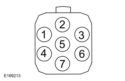 C543, pin 2, component side
|
|
C543, pin 3, component side
|
|
C634, pin 2, component side
|
|
C634, pin 3, component side
|
Is the resistance between 3 and 5 ohms?
| Yes |
GO to R10REPAIR the circuit in question.
|
| No |
INSTALL a new exterior door handle in question.
REFER to: Exterior Front Door Handle (501-14 Handles, Locks, Latches and Entry Systems, Removal and Installation).
|
|
| R10 CHECK THE EXTERIOR DOOR HANDLE ANTENNA CIRCUITS FOR A SHORT TO VOLTAGE |
|
NOTE:
After the RFA
module is disconnected, it is necessary to use the back-up method to
turn the ignition on by holding the passive key next to the PATS transceiver location and pressing the START/STOP button.
-
Disconnect
RFA Module C3503E
.
Is any voltage present?
| Yes |
REPAIR the circuit in question.
|
|
| R11 CHECK THE EXTERIOR DOOR HANDLE ANTENNA CIRCUITS FOR A SHORT TO GROUND |
Are the resistances greater than 10,000 ohms?
| No |
REPAIR the circuit in question.
|
|
| R12 CHECK THE EXTERIOR DOOR HANDLE ANTENNA CIRCUITS FOR AN OPEN |
Are the resistances less than 3 ohms?
| Yes |
INSTALL a new exterior front door handle.
REFER to: Exterior Front
Door Handle (501-14 Handles, Locks, Latches and Entry Systems, Removal
and Installation). TEST the system for normal operation. If the concern
is still present, GO to R13
|
| No |
REPAIR the circuit in question.
|
|
| R13 CHECK FOR CORRECT RFA (REMOTE FUNCTION ACTUATOR)
MODULE OPERATION |
-
Disconnect and inspect all the RFA module connectors.
-
Repair:
-
corrosion (install new connectors or terminals - clean module pins)
-
damaged or bent pins - install new terminals pins
-
pushed-out pins - install new pins as necessary
-
Reconnect the RFA module connectors and make sure they seat and latch correctly.
-
Operate the system and determine if the concern is still present.
Is the concern still present?
| Yes |
CHECK OASIS for any applicable Technical Service Bulletins (TSBs). If a
TSB exists for this concern, DISCONTINUE this test and FOLLOW TSB
instructions. If no Technical Service Bulletins (TSBs) address this
concern, INSTALL a new RFA module.
REFER to: Remote Function Actuator (RFA) Module (419-10 Multifunction Electronic Modules, Removal and Installation).
|
| No |
The system is operating correctly at this time. The
concern may have been caused by module connections. ADDRESS the root
cause of any connector or pin issues.
|
|
The Liftgate/Luggage Compartment Lid Passive Entry Feature Is Inoperative
Refer to Wiring Diagrams Cell 117 for schematic and connector information.
Normal Operations and Fault Conditions
REFER to: Handles, Locks, Latches and Entry Systems - System
Operation and Component Description (501-14 Handles, Locks, Latches and
Entry Systems, Description and Operation).
RFA Module DTC Fault Trigger Conditions
|
DTC
|
Description
|
Fault Trigger Conditions
|
|
B10C6:1F
|
Exterior Trunk Antenna: Circuit Intermittent
|
Sets when the RFA module detects an open or short from one of the keyless entry rear antenna circuits.
|
Possible Causes
-
Wiring, terminals or connectors
-
Keyless entry rear antenna
-
RFA module
PINPOINT TEST S: THE LIFTGATE/LUGGAGE COMPARTMENT LID PASSIVE ENTRY FEATURE IS INOPERATIVE
| S1 CHECK THE LIFTGATE/LUGGAGE COMPARTMENT LID LATCH RELEASE OPERATION |
-
Unlock the doors using the interior door lock control switch.
-
Press the liftgate/luggage compartment lid release button located on the rear of the vehicle.
Does the liftgate/luggage compartment lid latch release?
|
| S2 CHECK THE RKE (REMOTE KEYLESS ENTRY)
OPERATION |
-
Close the liftgate/luggage compartment lid.
-
Press the liftgate/luggage compartment lid release button twice on a key.
Does the liftgate/luggage compartment lid latch release?
|
| S3 CHECK THE LIFTGATE/LUGGAGE COMPARTMENT LID RELEASE SWITCH (TR_UNLK_H_SW) PID (PARAMETER IDENTIFICATION)
|
-
Using a diagnostic scan tool, view the RFA module Parameter Identifications (PIDs).
-
Using a diagnostic scan tool, monitor the RFA module PID TR_UNLK_H_SW.
-
Press and release the liftgate/luggage compartment lid release switch.
Does the PID correspond correctly when the liftgate/luggage compartment lid release switch is pressed?
|
| S4 CHECK THE LIFTGATE/LUGGAGE COMPARTMENT LID RELEASE SWITCH INPUT CIRCUIT FOR AN OPEN |
-
Disconnect Liftgate/Luggage Compartment Lid Release Switch C4224
.
-
Disconnect
RFA Module C3503B
.
-
Measure:
Click to display connectors
|
Positive Lead
|
Measurement / Action
|
Negative Lead
|
|
C4224-3
|
|
C3503B-9
|
Is the resistance less than 3 ohms?
|
| S5 CHECK THE KEYLESS ENTRY REAR ANTENNA |
-
Disconnect Keyless Entry Rear Antenna C4082
.
-
Measure:
|
Positive Lead
|
Measurement / Action
|
Negative Lead
|
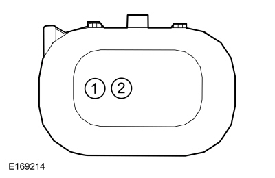 C4082 pin 1, component side
|
|
C4082 pin 2, component side
|
Is the resistance between 3 and 5 ohms?
| Yes |
INSTALL a new keyless entry rear antenna.
REFER to: Keyless Entry Rear Antenna (501-14 Handles, Locks, Latches and Entry Systems, Removal and Installation).
|
|
| S6 CHECK THE KEYLESS ENTRY REAR ANTENNA CIRCUITS FOR A SHORT TO VOLTAGE |
|
NOTE:
After the RFA
module is disconnected, it is necessary to use the back-up method to
turn the ignition on by holding the passive key next to the PATS transceiver location and pressing the START/STOP button.
-
Disconnect
RFA Module C3503E
.
-
Measure:
Click to display connectors
|
Positive Lead
|
Measurement / Action
|
Negative Lead
|
|
C4082-1
|
|
Ground
|
|
C4082-2
|
|
Ground
|
Is any voltage present?
| Yes |
REPAIR the circuit in question.
|
|
| S7 CHECK THE KEYLESS ENTRY REAR ANTENNA CIRCUITS FOR A SHORT TO GROUND |
-
Measure:
Click to display connectors
|
Positive Lead
|
Measurement / Action
|
Negative Lead
|
|
C4082-1
|
|
Ground
|
|
C4082-2
|
|
Ground
|
Are the resistances greater than 10,000 ohms?
| No |
REPAIR the circuit in question.
|
|
| S8 CHECK THE KEYLESS ENTRY REAR ANTENNA CIRCUITS FOR AN OPEN |
-
Measure:
Click to display connectors
|
Positive Lead
|
Measurement / Action
|
Negative Lead
|
|
C4082-1
|
|
C3503E-16
|
|
C4082-2
|
|
C3503E-7
|
Are the resistances less than 3 ohms?
| Yes |
INSTALL a new keyless entry rear antenna.
REFER to: Keyless Entry
Rear Antenna (501-14 Handles, Locks, Latches and Entry Systems, Removal
and Installation). TEST the system for normal operation. If the concern
is still present, GO to S9
|
| No |
REPAIR the circuit in question.
|
|
| S9 CHECK FOR CORRECT RFA (REMOTE FUNCTION ACTUATOR)
MODULE OPERATION |
-
Disconnect and inspect all the RFA module connectors.
-
Repair:
-
corrosion (install new connectors or terminals - clean module pins)
-
damaged or bent pins - install new terminals pins
-
pushed-out pins - install new pins as necessary
-
Reconnect the RFA module connectors and make sure they seat and latch correctly.
-
Operate the system and determine if the concern is still present.
Is the concern still present?
| Yes |
CHECK OASIS for any applicable Technical Service Bulletins (TSBs). If a
TSB exists for this concern, DISCONTINUE this test and FOLLOW TSB
instructions. If no Technical Service Bulletins (TSBs) address this
concern, INSTALL a new RFA module.
REFER to: Remote Function Actuator (RFA) Module (419-10 Multifunction Electronic Modules, Removal and Installation).
|
| No |
The system is operating correctly at this time. The
concern may have been caused by module connections. ADDRESS the root
cause of any connector or pin issues.
|
|
Special Tool(s) /
General Equipment
Flat-Bladed Screwdriver
Materials
Name
Specification
Motorcraft® Multi-Purpose Grease SprayXL-5-A
ESB-M1C93-B
Activation
NOTE:
Typical left front door shown, others similar...
Other information:
Removal
NOTE:
Removal steps in this procedure may contain installation details.
Disconnect the electrical connector, remove the retainers and the IAT sensor.
Torque:
44 lb.in (5 Nm)
Installation
To install, reverse the removal procedure...
B1414:11, B1414:93, B1419:11, B1419:93
Refer to Wiring Diagrams Cell 46 for schematic and connector information.
Normal Operation and Fault Conditions
The RCM monitors the driver front door and RH C-pillar side impact sensors and circuits for the following faults:
Open circuit
Short to voltage
Short to ground
Faulted driver front door ..
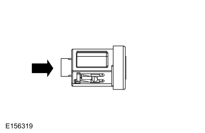
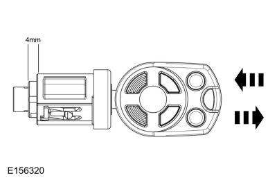
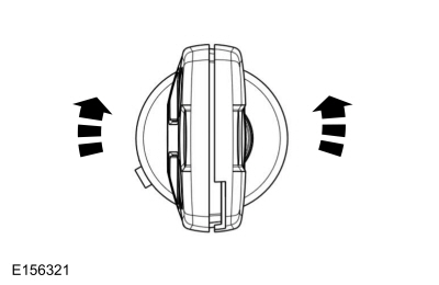

 Door Latch Lubrication. General Procedures