Ford Fiesta: Handles, Locks, Latches and Entry Systems / Ignition Lock Cylinder. Removal and Installation
Ford Fiesta 2014 - 2019 Service Manual / Body and Paint / Handles, Locks, Latches and Entry Systems / Ignition Lock Cylinder. Removal and Installation
Removal
Non-functional lock cylinder
NOTE: For non-functional ignition lock cylinders, replace the ingition lock cylinder housing.
-
Replace the ingition lock cylinder housing.
Refer to: Ignition Lock Cylinder Housing (211-05 Steering Wheel and Column Electrical Components, Removal and Installation).
Functional lock cylinder
-
Remove the Passive Anti-Theft System Transceiver (PATS).
Refer to: Passive Anti-Theft System (PATS) Transceiver (419-01B Passive Anti-Theft System (PATS) - Vehicles Without: Keyless Entry and Push Button Start, Removal and Installation).
Refer to: Passive Anti-Theft System (PATS) Transceiver (419-01C Passive Anti-Theft System (PATS) - Vehicles With: Keyless Entry and Push Button Start, Removal and Installation).
-
Remove the ignition lock cylinder.
-
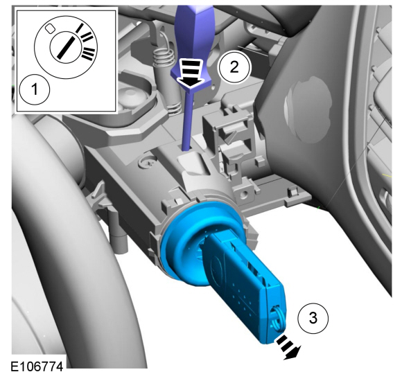
Insert the ignition key and position the ignition lock cylinder to the ACC position.
-
Using a suitable tool, press the ignition lock cylinder release pin through the access hole.
-
Pulling the ignition lock cylinder outward, remove the ignition lock cylinder.
-
Insert the ignition key and position the ignition lock cylinder to the ACC position.
 |
Installation
-
Make sure the ignition lock cylinder is in the ACC position.
-
Insert the ignition lock cylinder into the ignition lock
cylinder access hole located on the steering column. Make sure to align
the locking pin with the locking pin access hole.
-
Rotate the ignition key through all lock cylinder positions to check for correct operation.
-
Install the Passive Anti-Theft System Transceiver (PATS).
Refer to: Passive Anti-Theft System (PATS) Transceiver (419-01B Passive Anti-Theft System (PATS) - Vehicles Without: Keyless Entry and Push Button Start, Removal and Installation).
Refer to: Passive Anti-Theft System (PATS) Transceiver (419-01C Passive Anti-Theft System (PATS) - Vehicles With: Keyless Entry and Push Button Start, Removal and Installation).
 Front Door Lock Cylinder. Removal and Installation
Removal
NOTE:
LH side shown, RH side similar.
Remove the access plug and loosen the exterior front door handle retaining screw...
 Front Door Latch. Removal and Installation
Removal
NOTE:
Removal steps may contain installation details.
NOTE:
Driver side shown, passenger side similar.
All vehicles
Remove the front door trim panel...
Other information:
Ford Fiesta 2014 - 2019 Service Manual: Fuel Pump Driver Module (FPDM). Removal and Installation
Removal NOTE: The FPDM is located under the carpet and under left front seat attached to the rear of the front cross floor support in front of the left front seat. NOTE: Removal steps in this procedure may contain installation details...
Ford Fiesta 2014 - 2019 Service Manual: Wheel Cylinder. Removal and Installation
Removal NOTE: Removal steps in this procedure may include installation details. Refer to: Health and Safety Precautions (100-00 General Information, Description and Operation). Remove the brake drum. Refer to: Brake Drum (206-02 Drum Brake, Removal and Installation)...
Categories
- Manuals Home
- Ford Fiesta Service Manual (2014 - 2019)
- Manual Transmission, Clutch, Transfer Case and Power Transfer Unit
- Clutch - 6-Speed Manual Transmission – B6
- Engine Cooling - 1.6L EcoBoost (132kW/180PS) – Sigma
- Engine
- Service Information
Brake Backing Plate. Removal and Installation
Removal
NOTE: Removal steps in this procedure may contain installation details.
Remove the brake shoes.Refer to: Brake Shoes (206-02 Drum Brake, Removal and Installation).
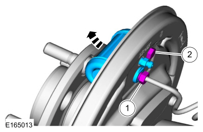
Disconnect the brake tube fitting.
Torque: 159 lb.in (18 Nm) Remove the bolt and wheel cylinder.
Torque: 106 lb.in (12 Nm)
 Disconnect the brake shoe lever fitting and re
Copyright © 2025 www.fofiesta7.com