Ford Fiesta: Front Drive Halfshafts / Halfshaft Bearing - 1.6L EcoBoost (132kW/180PS) – Sigma. Removal and Installation
Ford Fiesta 2014 - 2019 Service Manual / Driveline / Front Drive Halfshafts / Halfshaft Bearing - 1.6L EcoBoost (132kW/180PS) – Sigma. Removal and Installation
Special Tool(s) / General Equipment
 |
205-343
(T95P-3514-A)
Installer, Constant Velocity Joint Boot Clamp TKIT-1995-F TKIT-1995-FM/FLM TKIT-1995-LM/M |
 |
205-D064
(D84L-1123-A)
Puller, Bearing |
| Flat Headed Screw Driver | |
| Hydraulic Press | |
Materials
| Name | Specification |
|---|---|
| Motorcraft® Constant Velocity Joint Grease XG-5 |
WSS-M1C258-A1 |
Removal
-
Remove the front halfshaft RH .
Refer to: Front Halfshaft RH (205-04 Front Drive Halfshafts, Removal and Installation).
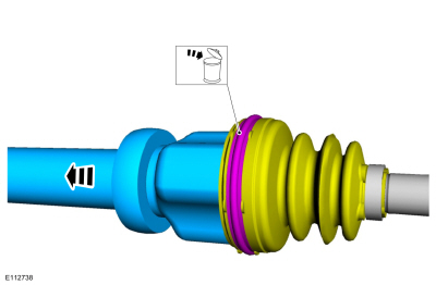
-
Remove and discard the CV joint boot clamp.
 |
-
Separate the tripod joint from the housing and wipeout all the grease.
 |
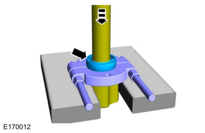
-
Using the Bearing Puller and a suitable press, remove the intermediate shaft bearing.
Use Special Service Tool: 205-D064 (D84L-1123-A) Puller, Bearing.
Use the General Equipment: Hydraulic Press
 |
Installation
-
Using a hydraulic press, install the intermediate shaft bearing.
Use the General Equipment: Hydraulic Press
 |
-
-
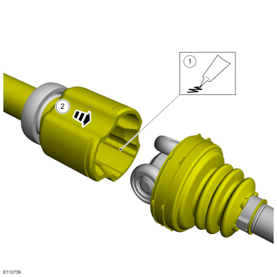
Apply the grease into the outer joint and CV joint boot.
Material: Motorcraft® Constant Velocity Joint Grease / XG-5 (WSS-M1C258-A1)
-
Connect the outer joint and CV joint boot.
-
Apply the grease into the outer joint and CV joint boot.
 |
-
-
Insert a small flat-blade screwdriver under the boot seat to allow the air to escape.
Use the General Equipment: Flat Headed Screw Driver
-
Completely slide the intermediate shaft into the CV tripod housing until it bottoms out.
-
Slide the intermediate shaft out 25mm (1 inch).
-
Remove the screwdriver.
-
Insert a small flat-blade screwdriver under the boot seat to allow the air to escape.
 |
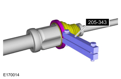
-
Using the special tool, install the new CV boot clamps.
Use Special Service Tool: 205-343 (T95P-3514-A) Installer, Constant Velocity Joint Boot Clamp.
 |
-
Install the front RH halfshaft.
Refer to: Front Halfshaft RH (205-04 Front Drive Halfshafts, Removal and Installation).
 Outer Constant Velocity (CV) Joint Boot. Removal and Installation
Special Tool(s) /
General Equipment
205-343
(T95P-3514-A)
Installer, Constant Velocity Joint Boot ClampTKIT-1995-FTKIT-1995-FM/FLMTKIT-1995-LM/M
Materials
Name
Specification
Motorcraft® Constant Velocity Joint GreaseXG-5
WSS-M1C258-A1
Removal
Remove the inner CV joint boot...
 Brake System
..
Other information:
Ford Fiesta 2014 - 2019 Service Manual: Front Fog Lamp Adjustment. General Procedures
Adjustment NOTE: Horizontal aim is not required for this vehicle and is not adjustable. Consult your state vehicle inspection center for recommended tolerance ranges for visual aiming. Before starting the fog lamp assembly adjustment: Check the tire inflation. Make sure there are no other loads in the vehicle other than a half tank of fuel...
Ford Fiesta 2014 - 2019 Service Manual: Rocker Panel - 5-Door. Removal and Installation
Special Tool(s) / General Equipment Resistance Spotwelding Equipment Hot Air Gun Air Body Saw MIG/MAG Welding Equipment Spot Weld Drill Bit Locking Pliers Folding Rule Materials Name Specification Metal Bonding AdhesiveTA-1, TA-1-B, 3M™ 08115, LORD Fusor® 108B, Henkel Teroson EP 5055 - Removal ..
Categories
- Manuals Home
- Ford Fiesta Service Manual (2014 - 2019)
- Camshafts. Removal and Installation
- Engine System - General Information
- Engine
- Service Information
- Clutch - 6-Speed Manual Transmission – B6
Component Bleeding. General Procedures
Special Tool(s) / General Equipment
Master Cylinder Bleeding SetBleeding
NOTICE: If the fluid is spilled on the paintwork, the affected area must be immediately washed down with cold water.
Master Cylinder
NOTE: When a new brake master cylinder has been installed, it should be primed to prevent air from entering the system.
NOTE: Make sure the area around the master cylinder cap is clean and free of foreign material.
Remove the brake fluid reservoir cap.Copyright © 2024 www.fofiesta7.com