Ford Fiesta: Engine - 1.6L EcoBoost (132kW/180PS) – Sigma / Engine. Removal
Special Tool(s) /
General Equipment
 |
300-OTC1585AE
Powertrain Lift |
 |
300-OTC1819E
2,200# Floor Crane, Fold Away |
 |
303-1502
Lifting Device Engine
TKIT-2012A-FL
TKIT-2012A-ROW |
 |
303-476
(T94P-9472-A)
Socket, Exhaust Gas Oxygen Sensor
TKIT-1994-LM/M
TKIT-1994-F
TKIT-1994-FLM/FM |
| Strap Wrench |
| Oil Drain Equipment |
| Cable Ties |
| Hose Clamp Remover/Installer |
| Wooden Block |
Materials
| Name |
Specification |
Motorcraft® Penetrating and Lock Lubricant
XL-1 |
-
|
-
With the vehicle in NEUTRAL, position it on a hoist.
Refer to: Jacking and Lifting - Overview (100-02 Jacking and Lifting, Description and Operation).
-
Release the fuel system pressure.
Refer to: Fuel System Pressure Release (310-00B Fuel System - General
Information - 1.6L EcoBoost (132kW/180PS) – Sigma, General Procedures).
-
Recover the refrigerant.
Refer to: Air Conditioning (A/C) System Recovery, Evacuation
and Charging (412-00 Climate Control System - General Information)
.
-
Drain the cooling system.
Refer to: Engine Cooling System Draining, Vacuum Filling and Bleeding
(303-03B Engine Cooling - 1.6L EcoBoost (132kW/180PS) – Sigma, General
Procedures).
-
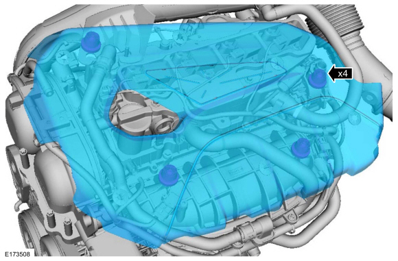
Remove the engine appearance cover.
-
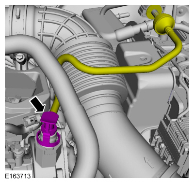
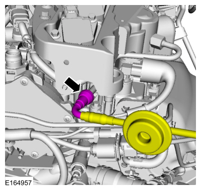
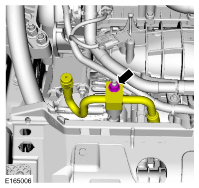
Disconnect the vacuum tube connector.
-
Remove the air cleaner.
Refer to: Air Cleaner (303-12B Intake Air Distribution and Filtering -
1.6L EcoBoost (132kW/180PS) – Sigma, Removal and Installation).
-
-
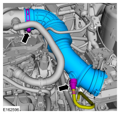
Disconnect the quick release coupling from the air cleaner outlet pipe.
-
Loosen the clamp and remove the air cleaner outlet pipe.
-
NOTICE:
Whenever turbocharger air intake system components are
removed, always cover open ports to protect from debris. It is important
that no foreign material enter the system. The turbocharger compressor
vanes are susceptible to damage from even small particles. All
components should be inspected and cleaned, if necessary, prior to
installation or reassembly.
-
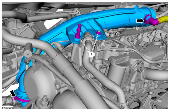
Remove the engine appearance cover stud and the nut.
-
Disconnect the crankcase ventilation tube, Loosen the clamp and remove the air cleaner outlet pipe.
-
Remove the battery tray.
Refer to: Battery Tray - 1.6L EcoBoost (132kW/180PS) – Sigma (414-01 Battery, Mounting and Cables, Removal and Installation).
-
-
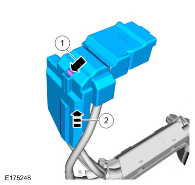
Release the tab.
-
Remove the battery terminal cover.
-
Remove the nut and the wire.
-
-
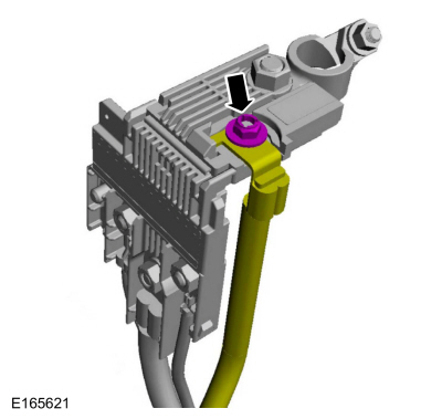
Disconnect the electrical connector.
-
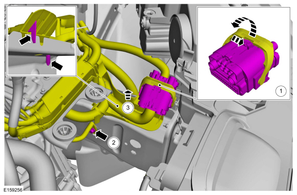
Remove the bolt and the ground wire.
-
Detach the wiring harness mounting retainers.
-
Remove the wiring harness mounting retainers.
-
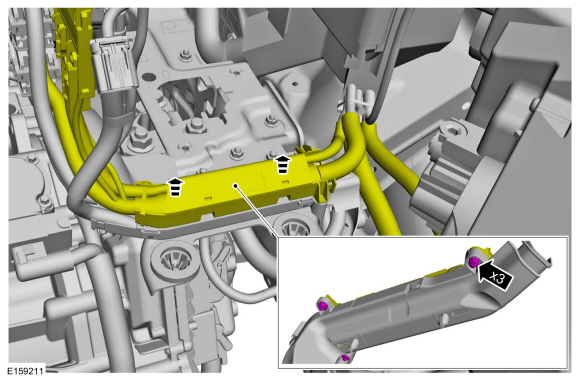
Detach the wiring harness mounting retainers.
-
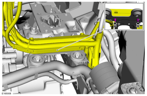
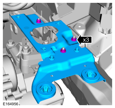
Remove the nuts and the bracket.
-
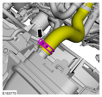
Disconnect the coolant hose.
Use the General Equipment: Hose Clamp Remover/Installer
-
NOTE:
Be prepared to collect escaping fluid.
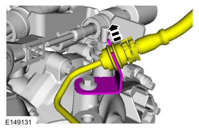
Early build vehicles, disconnect the fuel line connection.
Refer to: Quick Release Coupling (310-00B Fuel System - General
Information - 1.6L EcoBoost (132kW/180PS) – Sigma, General Procedures).
-
NOTE:
Be prepared to collect escaping fluid.
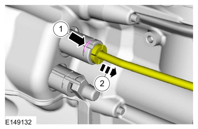
Late build vehicles, disconnect the fuel line connection.
Refer to: Spring Lock Couplings (310-00B Fuel System - General
Information - 1.6L EcoBoost (132kW/180PS) – Sigma, General Procedures).
-
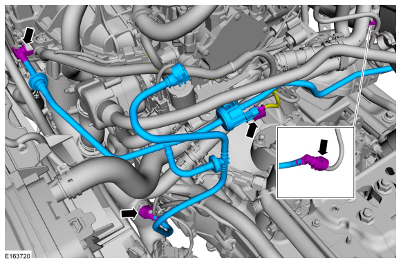
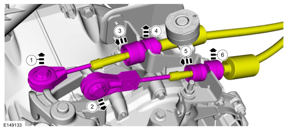
Disconnect the quick release couplings, electrical connector and remove the fuel evaporative tube assembly.
Refer to: Quick Release Coupling (310-00B Fuel System - General
Information - 1.6L EcoBoost (132kW/180PS) – Sigma, General Procedures).
-
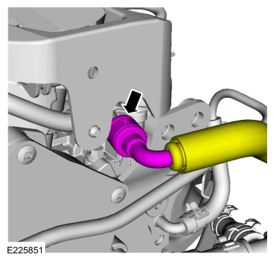
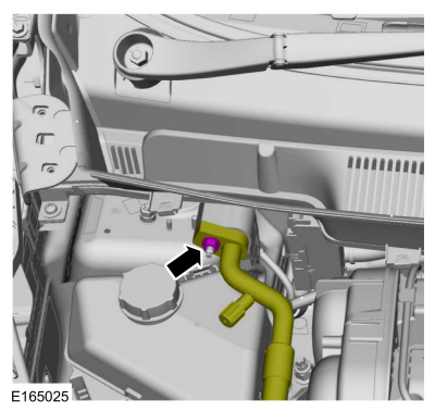
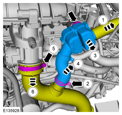
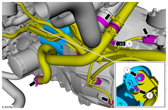
Disconnect the coolant tube and detach the retainer.
Use the General Equipment: Hose Clamp Remover/Installer
-
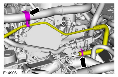
NOTE:
Note the position of the coolant hoses for installation.
Disconnect the heater hoses.
Use the General Equipment: Hose Clamp Remover/Installer
-
Disconnect the tube from the retaining clamp.
-
Disconnect the clutch cylinder fluid supply tube.
-
Disconnect the selector lever cables.
-
NOTE:
Discard the O-ring seal and gasket seal.
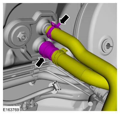
Remove the nut and disconnect the A/C line.
-
NOTE:
Discard the O-ring seal and gasket seal.
Remove the nut and disconnect the A/C line.
-
Remove the degas bottle.
Refer to: Degas Bottle (303-03B Engine Cooling - 1.6L EcoBoost (132kW/180PS) – Sigma, Removal and Installation).
-
-
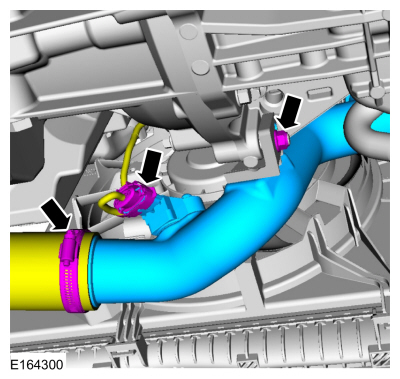
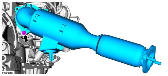
Disconnect the hose, loosen the hose clamp and remove the resonator assembly.
-
Loosen the hose clamp and position aside the trottle body hose.
-
-
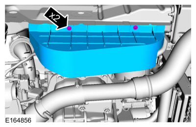
Loosen the clamp and disconnect the electrical connector.
-
Remove the nut and the CAC outlet pipe.
-
Remove the retainers and the shield.
-
-
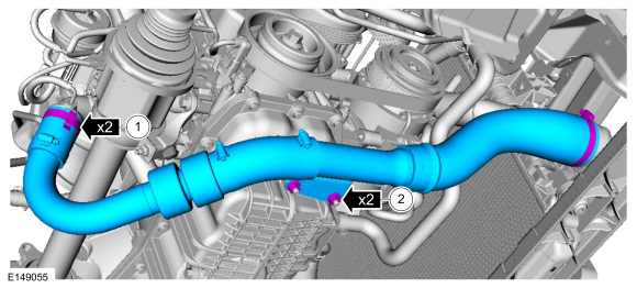
Loosen the clamps.
-
Remove the nuts and theTC outlet tube.
-
Remove the front subframe.
Refer to: Front Subframe (502-00 Uni-Body, Subframe and Mounting System, Removal and Installation).
-
Remove the drain plug and drain the engine oil, then install the drain plug.
Use the General Equipment: Oil Drain Equipment
Torque:
21 lb.ft (28 Nm)
-
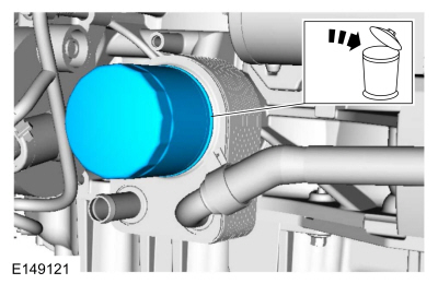
Remove and discard the engine oil filter.
Use the General Equipment: Strap Wrench
-
Drain the transmission fluid.
Refer to: Transmission Draining and Filling (308-03B Manual
Transmission - 6-Speed Manual Transmission – B6, General Procedures).
-
Remove and discard the halfshaft bearing retaining strap and the nuts.
-
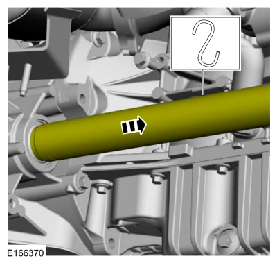
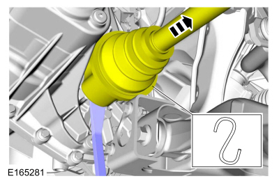
Remove and support the halfshaft from the transmission.
-
Using a pry bar, Separate the halfshaft from the transmission and support.
-
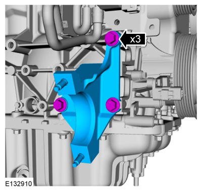
Remove the bolts and the bracket.
-
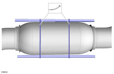
Support the exhaust flexible pipe with a support wrap or suitable splint.
Use the General Equipment: Cable Ties
-
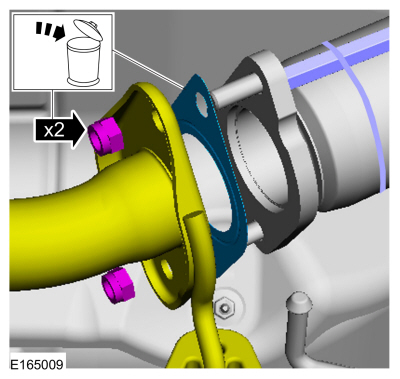
-
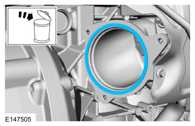
Position back the exhaust system, remove and discard the gasket.
-
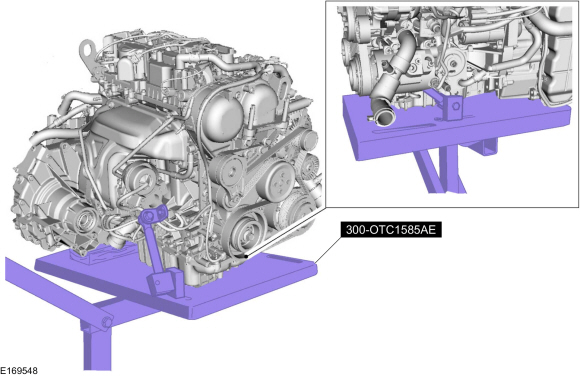
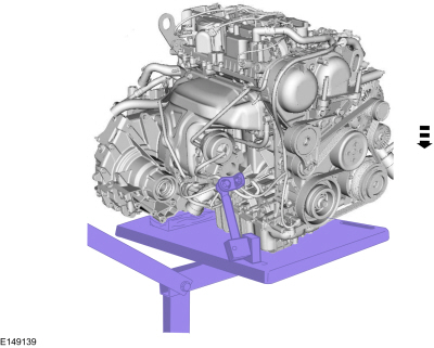
Install Special Service Tool: 300-OTC1585AE
Powertrain Lift.
Use the General Equipment: Wooden Block
-
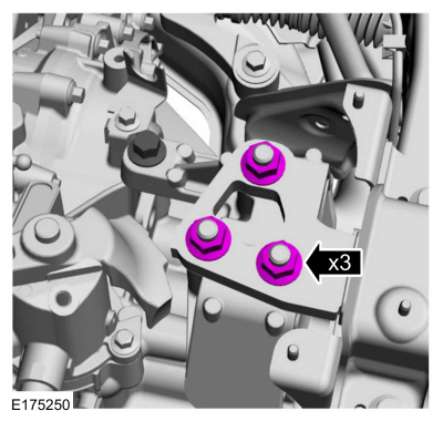
Remove the nuts.
-
-
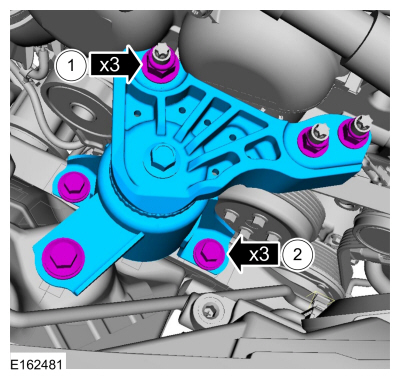
Remove the nuts.
-
Remove the bolts and the engine mount.
-
Using the special tool, lower the engine from the vehicle.
-
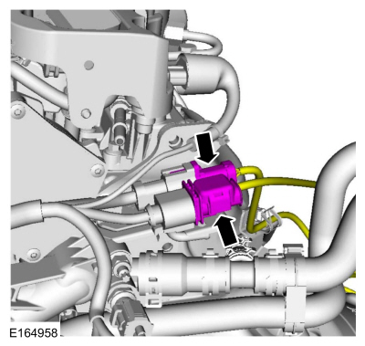
Disconnect the electrical connectors.
-
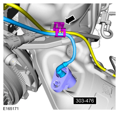
Using the special tool, remove the HO2S . Detach the wiring harness retainer.
Use Special Service Tool: 303-476
(T94P-9472-A)
Socket, Exhaust Gas Oxygen Sensor.
Material: Motorcraft® Penetrating and Lock Lubricant
/ XL-1
-
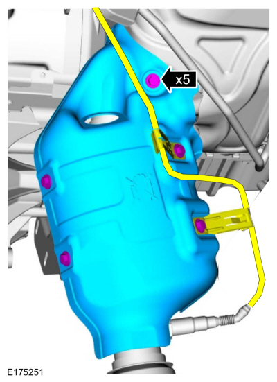
Remove the bolts and the heat shield.
-
Remove the catalytic converter bolts.
-
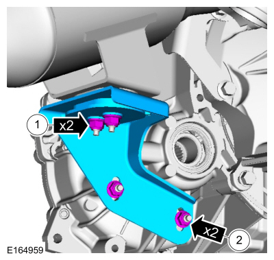
Remove the nuts and catalytic converter mount bracket.
-
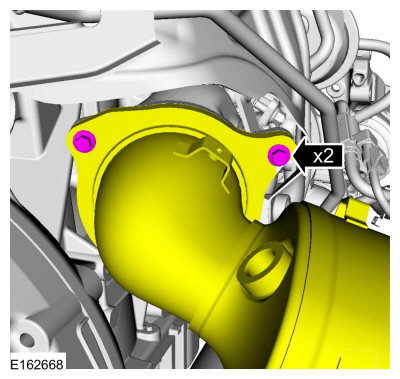
NOTE:
Support the catalytic converter while remove the bolt.
Remove the bolt and the catalytic converter.
-
Discard the catalytic convertor gasket.
-
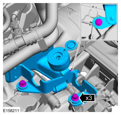
Remove the bolts and the bracket.
-
-
Remove the nut and the starter motor solenoid terminal wiring electrical connection.
-
Remove the nut and the starter motor solenoid terminal wiring electrical connection.
-
Loosen the clamp and disconnect the coolant hose and position aside. Remove the bolts and the starter motor.
Use the General Equipment: Hose Clamp Remover/Installer
-
Detach the wiring harness retainer. Disconnect the electrical connector.
-
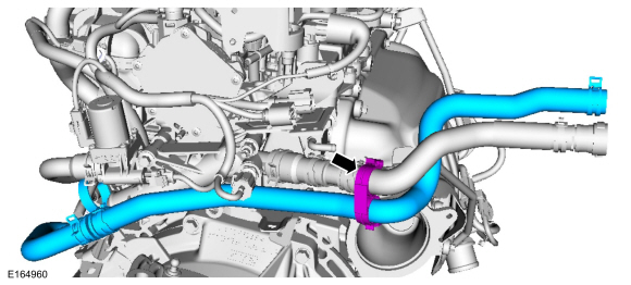
Detach the retainer and remove the coolant hose.
-
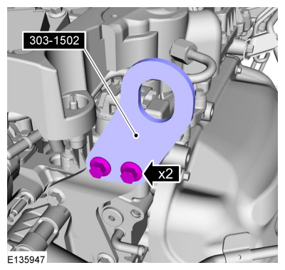
Install the engine lifting bracket and the bolts.
Install Special Service Tool: 303-1502
Lifting Device Engine.
-
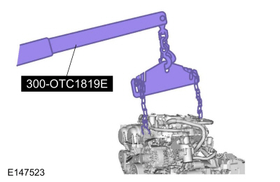
Install the engine floor crane.
Install Special Service Tool: 300-OTC1819E
2,200# Floor Crane, Fold Away.
-
Remove Special Service Tool: 300-OTC1585AE
Powertrain Lift.
-
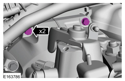
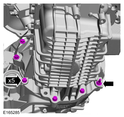
Remove the transmission bolts.
-
Remove the transmission bolts.
-
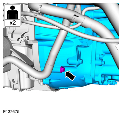
Remove the transmission-to-engine bolt and remove the transmission from the engine.
Special Tool(s) /
General Equipment
303-1097Locking Tool, Variable Camshaft Timing Oil Control UnitTKIT-2010B-FLMTKIT-2010B-ROW
303-1552Alignment Tool, CamshaftTKIT-2012A-FLTKIT-2012A-ROW
Removal
NOTICE:
Do not loosen or remove the crankshaft pulley bolt without
first installing the special tools...
Special Tool(s) /
General Equipment
100-001
(T50T-100-A)
Slide Hammer
300-OTC1819E2,200# Floor Crane, Fold Away
303-1097Locking Tool, Variable Camshaft Timing Oil Control UnitTKIT-2010B-FLMTKIT-2010B-ROW
303-1502Lifting Device EngineTKIT-2012A-FLTKIT-2012A-ROW
303-409
(T92C-6700-CH)
Remover, Crankshaft SealTKIT-1992-FH/FMH/FLMHTKIT-19..
Other information:
Removal
NOTE:
Removal steps in this procedure may contain installation details.
Remove the front bumper cover.
Refer to: Front Bumper Cover (501-19 Bumpers, Removal and Installation).
Remove the retainers and the lower air deflector.
Both sides.
Loosen the clamps and disconnect the CAC outlet and in..
Removal
NOTE:
Removal steps in this procedure may contain installation details.
Remove the engine appearance cover.
Remove the air cleaner outlet pipe.
Refer to: Air Cleaner Outlet Pipe (303-12B Intake Air Distribution and
Filtering - 1.6L EcoBoost (132kW/180PS) – Sigma, Removal and
Installation).
..


 Variable Camshaft Timing (VCT) Unit. Removal and Installation
 Engine. Disassembly