Ford Fiesta: Engine - 1.6L EcoBoost (132kW/180PS) – Sigma / Crankshaft Rear Seal. Removal and Installation
Ford Fiesta 2014 - 2019 Service Manual / Engine / Engine - 1.6L EcoBoost (132kW/180PS) – Sigma / Crankshaft Rear Seal. Removal and Installation
Removal
-
Remove the following items:
-
Remove the flywheel.
Refer to: Flywheel (303-01A Engine - 1.6L Duratec-16V Ti-VCT (88kW/120PS) – Sigma, Removal and Installation).
-
Remove the oil pan.
Refer to: Oil Pan (303-01A Engine - 1.6L Duratec-16V Ti-VCT (88kW/120PS) – Sigma, Removal and Installation).
-
Remove the flywheel.
-
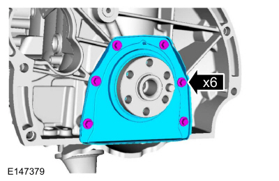
Remove the bolts and the crankshaft rear seal.
 |
Installation
-
NOTE: Make sure that the mating faces are clean and free of foreign material.
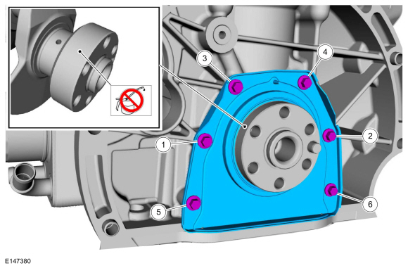
NOTE: The new crankshaft rear seal is supplied with an alignment sleeve which must be removed after installation.
NOTE: Do not remove the alignment sleeve from the crankshaft rear seal prior to installation on the crankshaft.
Install the rear crankshaft seal and the bolts in sequence shown.
Torque:
Stage 1: Tighten bolts 1 through 6 to:: 35 lb.in (4 Nm)
Stage 2: Tighten bolts 1 through 6 to:: 89 lb.in (10 Nm)
 |
-
Install the following items:
-
Install the oil pan.
Refer to: Oil Pan (303-01A Engine - 1.6L Duratec-16V Ti-VCT (88kW/120PS) – Sigma, Removal and Installation).
-
Install the flywheel.
Refer to: Flywheel (303-01A Engine - 1.6L Duratec-16V Ti-VCT (88kW/120PS) – Sigma, Removal and Installation).
-
Install the oil pan.

 Camshafts. Removal and Installation
Special Tool(s) /
General Equipment
303-1532Installer, Camshaft SealTKIT-2010B-FLMTKIT-2010B-ROW
303-393-02Adapter for 303-393TKIT-2012A-FLTKIT-2012A-ROW
303-393ALocking Tool, FlywheelTKIT-2012A-FLTKIT-2012A-ROW
303-409
(T92C-6700-CH)
Remover, Crankshaft SealTKIT-1992-FH/FMH/FLMHTKIT-1993-LMH/MH
303-748Locking Tool, CrankshaftTKIT-2010B-F..
Other information:
Ford Fiesta 2014 - 2019 Service Manual: Parking Aid Camera. Removal and Installation
Removal Remove the luggage compartment lid moulding. Refer to: Luggage Compartment Lid Moulding - 4-Door (501-08 Exterior Trim and Ornamentation, Removal and Installation). Refer to: Luggage Compartment Lid Moulding - 5-Door (501-08 Exterior Trim and Ornamentation, Removal and Installation). NOTE: 5-door is shown, 4-door is similar. Remove the parkin..
Ford Fiesta 2014 - 2019 Service Manual: Rear Door. Removal and Installation
Removal NOTE: LH side shown, RH side similar. NOTE: 5-door shown, 4-door similar. NOTE: Removal steps in this procedure may contain installation details. Remove the check arm bolt. Torque: 18 lb.ft (25 Nm) Disconnect the rear door electrical connector. ..
Categories
- Manuals Home
- Ford Fiesta Service Manual (2014 - 2019)
- Engine System - General Information
- Valve Clearance Adjustment. General Procedures
- Timing Belt. Removal and Installation
- Service Information
- General Information
Brake Drum. Removal and Installation
Removal
NOTE: Removal steps in this procedure may contain installation details.
 WARNING:
Before beginning any service procedure in this
manual, refer to health and safety warnings in section 100-00 General
Information. Failure to follow this instruction may result in serious
personal injury.
WARNING:
Before beginning any service procedure in this
manual, refer to health and safety warnings in section 100-00 General
Information. Failure to follow this instruction may result in serious
personal injury.
Remove the wheel and tire.
Refer to: Wheel and Tire (204-04A Wheels and Tires, Removal and Installation).
Copyright © 2025 www.fofiesta7.com