Ford Fiesta: Fuel Charging and Controls - Turbocharger - 1.6L EcoBoost (132kW/180PS) – Sigma / Turbocharger. Removal and Installation
Materials
| Name | Specification |
|---|---|
| Engine Oil - SAE 5W-20 - Synthetic Blend Motor Oil XO-5W20-Q1SP |
WSS-M2C945-B1 |
Removal
NOTICE: Whenever turbocharger air intake system components are removed, always cover open ports to protect from debris. It is important that no foreign material enter the system. The turbocharger compressor vanes are susceptible to damage from even small particles. All components should be inspected and cleaned, if necessary, prior to installation or reassembly.
NOTE: Removal steps in this procedure may contain installation details.
-
Remove the air cleaner outlet pipe.
Refer to: Air Cleaner Outlet Pipe (303-12B Intake Air Distribution and Filtering - 1.6L EcoBoost (132kW/180PS) – Sigma, Removal and Installation).
-
Drain the cooling system.
Refer to: Engine Cooling System Draining, Vacuum Filling and Bleeding (303-03B Engine Cooling - 1.6L EcoBoost (132kW/180PS) – Sigma, General Procedures).
-
Remove the degas bottle.
Refer to: Degas Bottle (303-03B Engine Cooling - 1.6L EcoBoost (132kW/180PS) – Sigma, Removal and Installation).
-
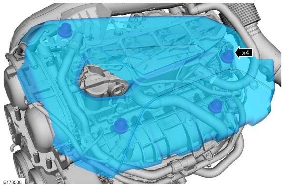
Remove the engine appearance cover.
 |
-
-
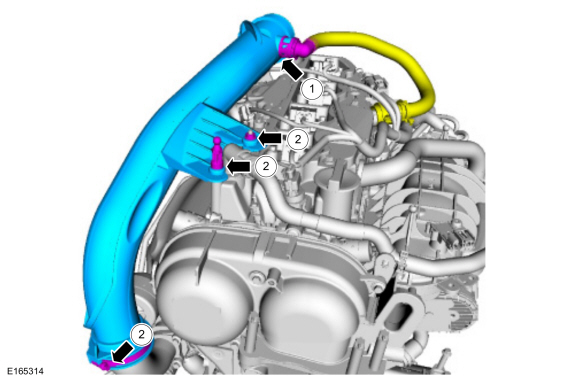
Disconnect the crankcase ventilation tube quick release coupling.
Refer to: Quick Release Coupling (310-00B Fuel System - General Information - 1.6L EcoBoost (132kW/180PS) – Sigma, General Procedures).
-
Remove the TC air inlet pipe retaining nut, the ball stud and loosen
the TC air inlet pipe clamp, then remove the TC inlet pipe.
Torque: 44 lb.in (5 Nm)
-
Disconnect the crankcase ventilation tube quick release coupling.
 |
-
Position the vehicle on a hoist.
Refer to: Jacking and Lifting - Overview (100-02 Jacking and Lifting, Description and Operation).
-
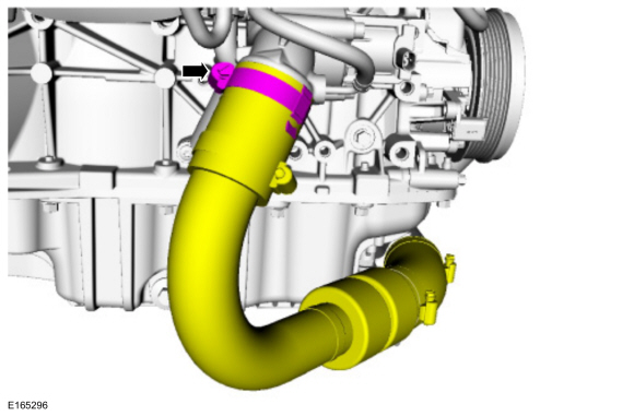
Loosen the clamp and position aside the TC outlet pipe out of the way.
Torque: 44 lb.in (5 Nm)
 |
-
-
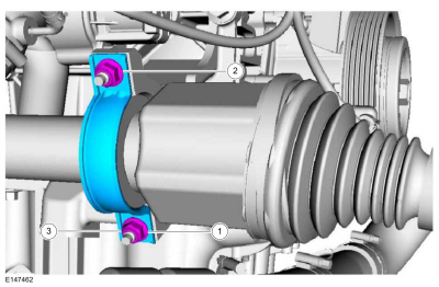
Remove and discard the front axle shaft bearing bracket lower nut.
-
Remove and discard the front axle shaft bearing bracket upper nut.
-
Remove and discard the front axle shaft bearing bracket.
Torque:
Tighten the lower nut: 44 lb.in (5 Nm)
Tighten the upper nut: 18 lb.ft (25 Nm)
Re-tighten the lower nut: 18 lb.ft (25 Nm)
-
Remove and discard the front axle shaft bearing bracket lower nut.
 |
-
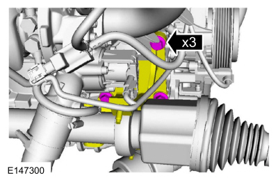
NOTE: It may be necessary to rotate the fail-safe to remove the front lower bolt.
Remove the front axle shaft bearing bracket bolts and then position the axle shaft bearing bracket out of the way.
Torque: 35 lb.ft (48 Nm)
 |
-
Remove the catalytic converter.
Refer to: Catalytic Converter (309-00B Exhaust System - 1.6L EcoBoost (132kW/180PS) – Sigma, Removal and Installation).
-
-
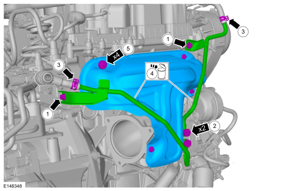
Remove the TC coolant tube bracket bolts.
Torque: 17 lb.ft (23 Nm)
-
Disconnect the TC coolant tube bolts from the TC .
Torque: 21 lb.ft (28 Nm)
-
Release the clanps and then disconnect the TC coolant tubes.
-
Remove and discard the TC coolant tubes.
-
Remove the TC heat shield bolts and then remove the TC heat shield.
Torque: 159 lb.in (18 Nm)
-
Remove the TC coolant tube bracket bolts.
 |
-
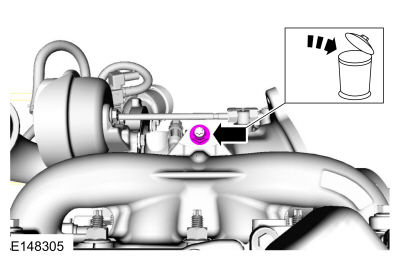
Remove and discard the TC mounting nut.
Torque: 18 lb.ft (25 Nm)
 |
-
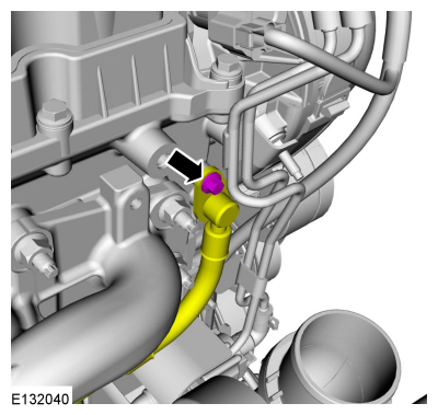
Remove the TC oil supply tube bolt and then position the TC oil supply tube aside.
Torque: 89 lb.in (10 Nm)
 |
-
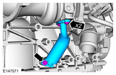
Remove the TC oil drain tube bolts and then remove the TC oil drain tube.
Torque: 89 lb.in (10 Nm)
 |
-
-
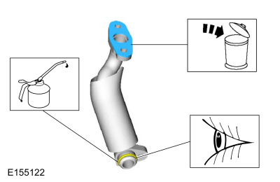
Remove and discard the TC oil drain tube gasket. Inspect and replace the TC oil return tube O-ring seal as needed.
-
To install, lubricate the TC oil return tube O-ring seal with clean engine oil.
Material: Engine Oil - SAE 5W-20 - Synthetic Blend Motor Oil / XO-5W20-Q1SP (WSS-M2C945-B1)
-
Remove and discard the TC oil drain tube gasket. Inspect and replace the TC oil return tube O-ring seal as needed.
 |
-
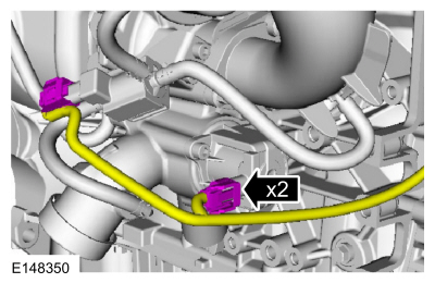
Disconnect the TC electrical connectors.
 |
-
-
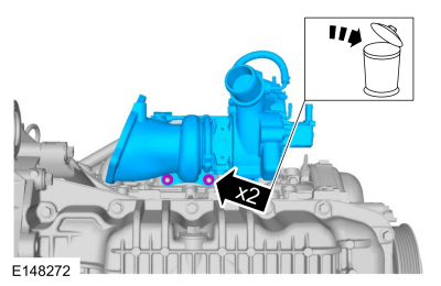
Remove and discard the TC mounting nuts and remove the TC .
Torque:
Stage 1: 18 lb.ft (25 Nm)
Stage 2: 18 lb.ft (25 Nm)
-
Remove and discard the TC mounting nuts and remove the TC .
 |
-
-
Remove and discard the TC mounting stud and the gasket.
Torque: 177 lb.in (20 Nm)
-
Replace the TC oil supply tube assembly, then install and tighten the TC oil supply tube bolt.
Torque: 19 lb.ft (26 Nm)
-
Lubricate the new TC oil supply tube O-ring seal with clean engine oil.
Material: Engine Oil - SAE 5W-20 - Synthetic Blend Motor Oil / XO-5W20-Q1SP (WSS-M2C945-B1)
-
Remove and discard the TC mounting stud and the gasket.
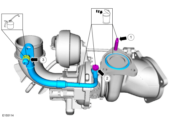 |
-
Remove and discard the TC mounting studs.
Torque: 177 lb.in (20 Nm)
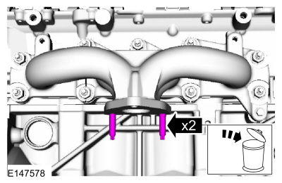 |
Installation
-
NOTICE: Make sure that the mating faces are clean and free of foreign material.
To install, reverse the removal procedure.
 Turbocharger - System Operation and Component Description. Description and Operation
System Operation
Refer to Powertrain Control/Emissions Diagnosis (PC/ED) manual. See Section 1 Description and Operation.
Component Description
Refer to Powertrain Control/Emissions Diagnosis (PC/ED) manual...
Other information:
Ford Fiesta 2014 - 2019 Service Manual: Lower Arm. Removal and Installation
Removal NOTICE: Suspension fasteners are critical parts that affect performance of vital components and systems. Failure of these fasteners may result in major service expense. Use the same or equivalent parts if replacement is necessary. Do not use a replacement part of lesser quality or substitute design. Tighten fasteners as specified. Remove the wheel and tire. R..
Ford Fiesta 2014 - 2019 Service Manual: Brake Disc. Removal and Installation
Materials Name Specification Motorcraft® DOT 4 LV High Performance Motor Vehicle Brake FluidPM-20 WSS-M6C65-A2 Motorcraft® Metal Brake Parts CleanerPM-4-A, PM-4-B, APM-4-C - Removal NOTE: Removal steps in this procedure may contain installation details. WARNING: Before beginning any service procedure in th..
Categories
- Manuals Home
- Ford Fiesta Service Manual (2014 - 2019)
- Engine. Assembly
- Maintenance Schedules - Gasoline Engines. Description and Operation
- General Information
- Valve Clearance Adjustment. General Procedures
- Engine
Brake Drum. Removal and Installation
Removal
NOTE: Removal steps in this procedure may contain installation details.
 WARNING:
Before beginning any service procedure in this
manual, refer to health and safety warnings in section 100-00 General
Information. Failure to follow this instruction may result in serious
personal injury.
Remove the wheel and tire.
Refer to: Wheel and Tire (204-04A Wheels and Tires, Removal and Installation).

