Ford Fiesta: Manual Transmission - 6-Speed Manual Transmission – B6 / Transmission. Assembly
Special Tool(s) / General Equipment
 |
100-002
(TOOL-4201-C)
Holding Fixture with Dial Indicator Gauge |
 |
205-075 Installer, Rear Wheel Hub Seal |
 |
205-081A Installer, Differential Bearing |
 |
205-115 Installer, Drive Pinion Seal TKIT-2000-F/FM/FLM |
 |
303-350
(T89P-6565-A)
Compressor, Valve Spring TKIT-1990-LMH TKIT-1989-F TKIT-1989-FM TKIT-1989-FLM |
 |
307-003
(T57L-500-B)
Holding Fixture, Transmission |
 |
307-680 Table, Assembly (DPS6) TKIT-2010D-FLM TKIT-2010D-ROW |
 |
308-847 Installer, Inputshaft Seal |
 |
308-849 Installer Shift Shaft Bushing |
 |
308-880 Installer, Driveshaft Seal |
 |
308-S217
(T94P-4451-BH)
Shim Selection Set TKIT-1994-LMH/MH2 TKIT-1994-FH/FMH/FLMH |
| Hot Air Gun | |
| Punch | |
| Adhesive Tape | |
Materials
| Name | Specification |
|---|---|
| Motorcraft® Gasket Maker TA-16 |
WSK-M2G348-A5 |
| Motorcraft® Dual Clutch Transmission Fluid XT-11-QDC |
WSS-M2C200-D2 |
| Motorcraft® Silicone Brake Caliper Grease and Dielectric Compound XG-3-A |
ESA-M1C200-A ESE-M1C171-A |
-
-
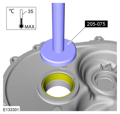
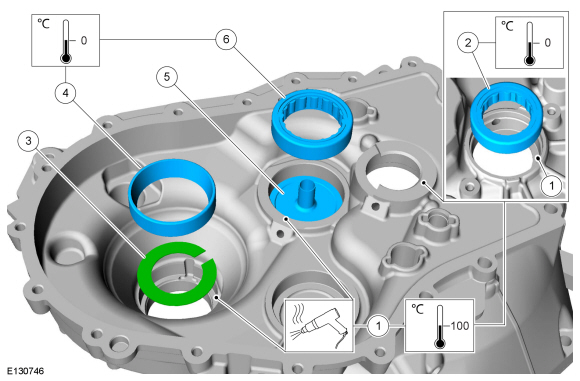
NOTE: In order to avoid incorrect readings, do not lubricate the taper roller bearings.
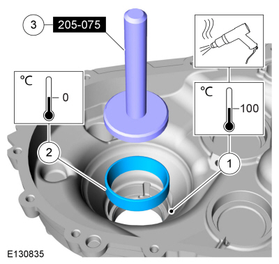
NOTE: Heat the clutch housing for no more then 3 minutes and no higher then 100 degrees Celsius / 212 degrees Fahrenheit
Heat the clutch housing.
Use the General Equipment: Hot Air Gun
-
Cool the bearing cup.
-
Using the special tool, install the bearing cup in the clutch housing.
Use Special Service Tool: 205-075 Installer, Rear Wheel Hub Seal.
-
 |
-
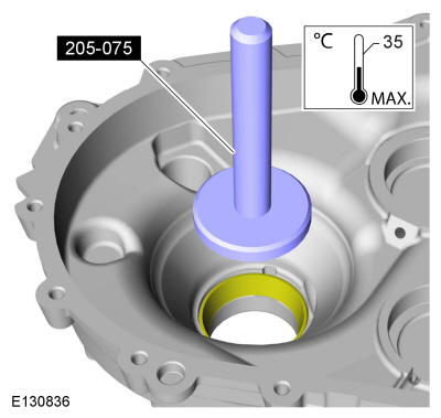
After the clutch housing cools, verify that the bearing cup is seated in the clutch housing.
Use Special Service Tool: 205-075 Installer, Rear Wheel Hub Seal.
 |
-
-
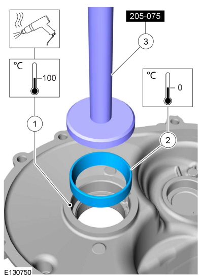
NOTE: Heat the transmission case for no more then 3 minutes and no higher then 100 degrees Celsius / 212 degrees Fahrenheit
Heat the transmission case.
Use the General Equipment: Hot Air Gun
-
Cool the bearing cup.
-
Using the special tool, install the bearing cup in the transmission case.
Use Special Service Tool: 205-075 Installer, Rear Wheel Hub Seal.
-
 |
-
After the transmission case cools, verify that the bearing cup is seated in the transmission case.
Use Special Service Tool: 205-075 Installer, Rear Wheel Hub Seal.
 |
-
NOTICE: The surfaces must be thoroughly cleaned or an inaccurate pre-load measurement can occur causing failure of the differential bearings.
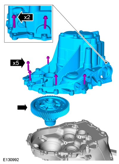
Install the differential in the clutch housing, install the transmission case and install every other bolt. Tighten the bolts in a crisscross sequence.
Torque: 159 lb.in (18 Nm)
 |
-
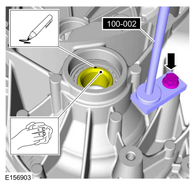
Clean the end face of the differential assembly and mark it at one place. Install the special tool.
Install Special Service Tool: 100-002 (TOOL-4201-C) Holding Fixture with Dial Indicator Gauge.
 |
-
Set up the dial indicator on the marked spot. Pre-load the dial gauge to 1 mm and zero it.
Install Special Service Tool: 100-002 (TOOL-4201-C) Holding Fixture with Dial Indicator Gauge.
 |
-
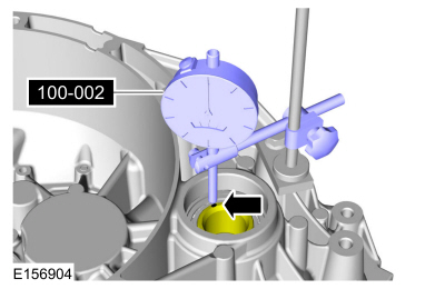
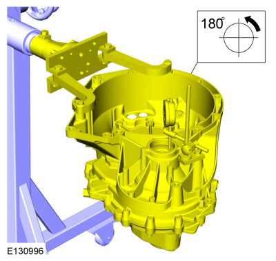
Rotate the transmission 180°.
 |
-
-
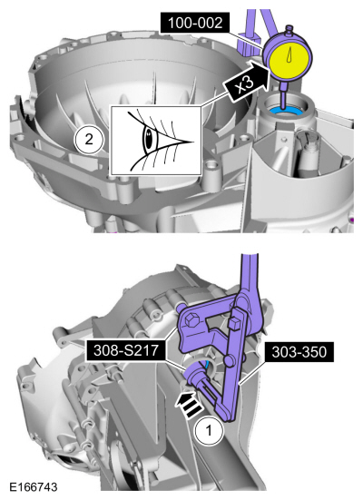
Using the special tool, apply pressure to the differential.
Use Special Service Tool: 303-350 (T89P-6565-A) Compressor, Valve Spring. , 308-S217 (T94P-4451-BH) Shim Selection Set.
-
Measure the differential end float: Make a note of the measurement.
Use Special Service Tool: 100-002 (TOOL-4201-C) Holding Fixture with Dial Indicator Gauge.
-
Repeat this step 3 times and average the measurements.
Example: 0.265 mm + 0.255 mm + 0.260 mm, divided by 3 = 0.260 mm.
-
Using the special tool, apply pressure to the differential.
 |
-
-
Determine the thickness of the differential adjusting shim:
-
Determined differential end float is X mm.
-
Differential bearing pre-load 0.14 mm.
-
Required adjusting shim thickness: X mm + 0.14 mm.
-
Determine adjusting shim thickness.
-
If the determined adjusting shim thickness is unequal, then use the next closest thickness of adjusting shim.
-
Determine the thickness of the differential adjusting shim:
- Remove Special Service Tool: 100-002 (TOOL-4201-C) Holding Fixture with Dial Indicator Gauge.
-
Remove the bolts, the transmission case and the differential.
|
-
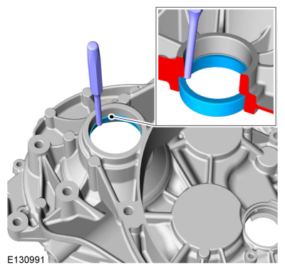
Using a punch, drive the differential bearing cup out of the clutch housing.
Use the General Equipment: Punch
 |
-
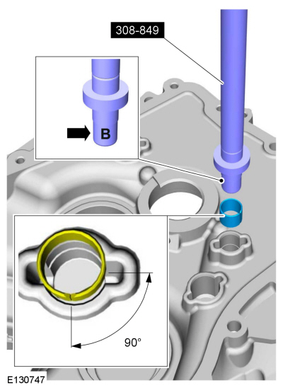
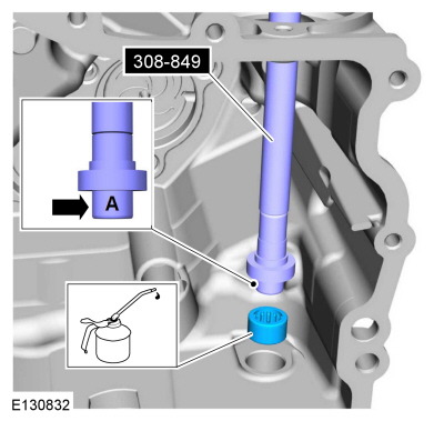
Using the special tool, install the shift rod bushing in the
clutch housing. Make sure the bushing is in the correct orientation as
shown.
Use Special Service Tool: 308-849 Installer Shift Shaft Bushing.
 |
-
-
NOTE: Heat the clutch housing for no more then 3 minutes and no higher then 100 degrees Celsius / 212 degrees Fahrenheit
Heat the clutch housing.
Use the General Equipment: Hot Air Gun
-
Cool the new input shaft roller bearing and install it in the clutch housing.
-
Install a new adjusting shim.
-
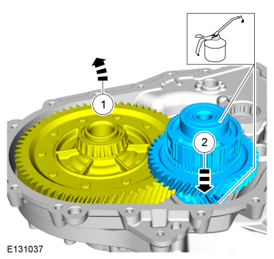
Cool the new differential bearing cup and install it in the clutch housing.
-
Install a new lube funnel in the clutch housing.
-
Cool the output shaft roller bearing and install it in the clutch housing.
-
 |
-
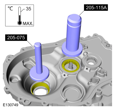
After the clutch housing cools, verify that the bearing is seated in the clutch housing.
Use Special Service Tool: 205-081A Installer, Differential Bearing.
 |
-
After the clutch housing cools, verify that the bearing and bearing race are seated in the clutch housing.
Use Special Service Tool: 205-075 Installer, Rear Wheel Hub Seal. , 205-115 Installer, Drive Pinion Seal.
 |
-
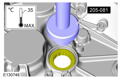
Using the special tools, install the selector mechanism bearing.
Use Special Service Tool: 308-849 Installer Shift Shaft Bushing.
Material: Motorcraft® Dual Clutch Transmission Fluid / XT-11-QDC (WSS-M2C200-D2)
 |
-
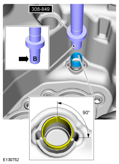
Using the special tool, install the shift rod bushing in the
transmission case. Make sure the bushing is in the correct orientation
as shown.
Use Special Service Tool: 308-849 Installer Shift Shaft Bushing.
 |
-
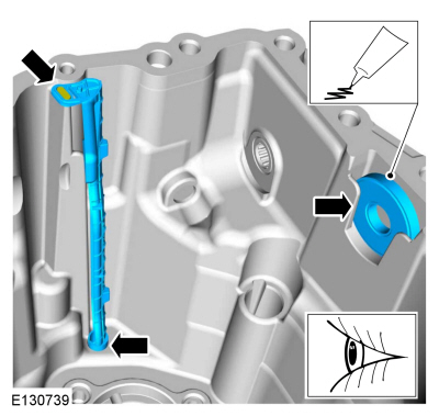
NOTE: Install the lube tube in the same position as noted during disassembly.
Install the lube tube and the magnet in the transmission case.
Material: Motorcraft® Silicone Brake Caliper Grease and Dielectric Compound / XG-3-A (ESA-M1C200-A) (ESE-M1C171-A)
 |
-
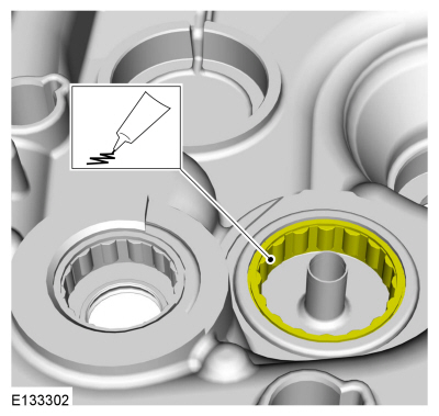
Lubricate the output shaft roller bearing.
Material: Motorcraft® Silicone Brake Caliper Grease and Dielectric Compound / XG-3-A (ESA-M1C200-A) (ESE-M1C171-A)
 |
-
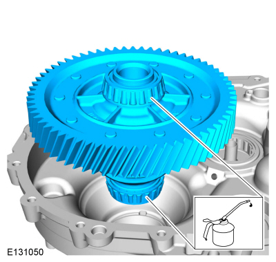
Lubricate the bearings and install the differential.
Material: Motorcraft® Dual Clutch Transmission Fluid / XT-11-QDC (WSS-M2C200-D2)
 |
-
-
Position the differential aside.
-
NOTICE: Be careful not to damage the roller bearing when installing the reverse idler gear.
Lubricate and install the reverse idler gear.
Material: Motorcraft® Dual Clutch Transmission Fluid / XT-11-QDC (WSS-M2C200-D2)
-
Position the differential aside.
 |
-
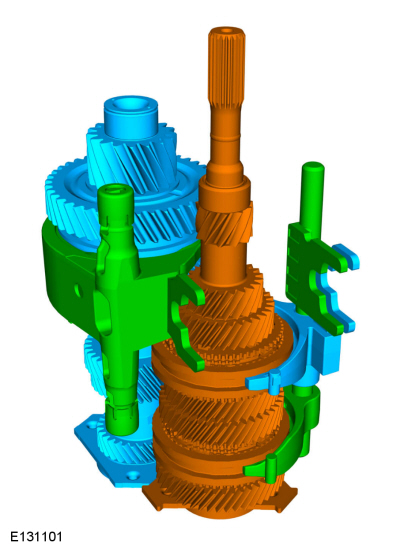
Assemble the input shaft, output shaft and the shift forks.
 |
-
-
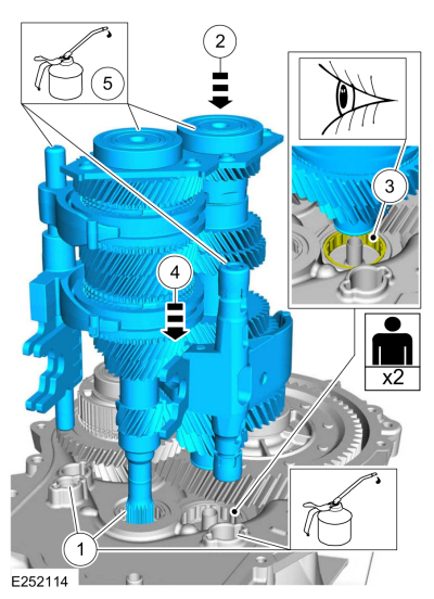
Lubricate the input shaft bearing and the shift rod bushing.
Material: Motorcraft® Dual Clutch Transmission Fluid / XT-11-QDC (WSS-M2C200-D2)
-
NOTICE: Be careful not to damage the bearings when installing the input shaft, output shaft and shift forks.
Position the input shaft, output shaft and shift forks into the clutch housing.
-
NOTICE: Make sure the output shaft is aligned with the bearing so damage does not occur to the output shaft bearing.
With the help of an assisstant, align the output shaft with the output shaft roller bearing.
-
Gently lower the input shaft, output shaft and shift forks and install them in the clutch housing.
-
Lubricate the input shaft and output shaft rear bearings.
Material: Motorcraft® Dual Clutch Transmission Fluid / XT-11-QDC (WSS-M2C200-D2)
-
Lubricate the input shaft bearing and the shift rod bushing.
 |
-
-
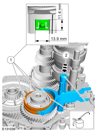
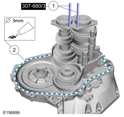
Lubricate the reverse synchronizer sleeve detents in
transmission fluid and install them so they fit in the reverse
synchronizer hub as shown.
-
Install the reverse synchronizer sleeve and reverse shift fork.
Material: Motorcraft® Dual Clutch Transmission Fluid / XT-11-QDC (WSS-M2C200-D2)
-
Lubricate the reverse synchronizer sleeve detents in
transmission fluid and install them so they fit in the reverse
synchronizer hub as shown.
 |
-
-
Install the special tools.
Install Special Service Tool: 307-680 Table, Assembly (DPS6).
-
Apply flange sealant to the clutch housing.
Material: Motorcraft® Gasket Maker / TA-16 (WSK-M2G348-A5)
-
Install the special tools.
 |
-
-
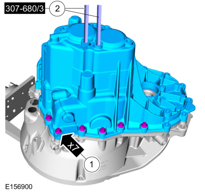
NOTICE: Make sure that new bolts are installed.
Install the transmission case and install new bolts.
Torque:
Stage 1: 159 lb.in (18 Nm)
Stage 2: 90°
- Remove Special Service Tool: 307-680 Table, Assembly (DPS6).
-
 |
-
-
NOTICE: Make sure that new bolts are installed.
Install new transmission case bolts.
Torque:
Stage 1: 159 lb.in (18 Nm)
Stage 2: 90°
-
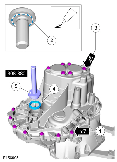
NOTICE: Make sure that new bolts are installed.
Apply sealant to the underside of the bolts.
Material: Motorcraft® Gasket Maker / TA-16 (WSK-M2G348-A5)
-
Install new bolts.
Torque: 177 lb.in (20 Nm)
-
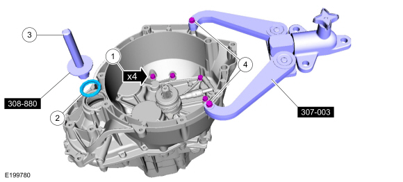
Position a new seal on the transmission case.
-
Using the special tool, install a new seal in the transmission case
Use Special Service Tool: 308-880 Installer, Driveshaft Seal.
-
 |
-
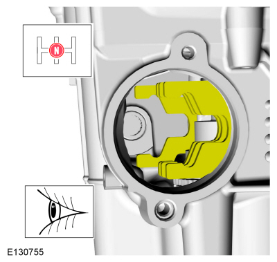
Make sure the transmission is in neutral.
 |
-
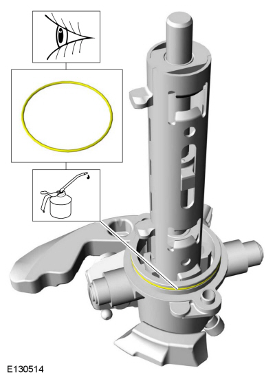
NOTE: Re-use the O-ring seal unless it is damaged.
Lubricate and install the O-ring.
Material: Motorcraft® Dual Clutch Transmission Fluid / XT-11-QDC (WSS-M2C200-D2)
 |
-
-
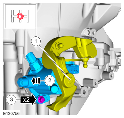
Make sure that the shift forks are in the neutral (N) position.
-
NOTICE: Make sure that no components catch.
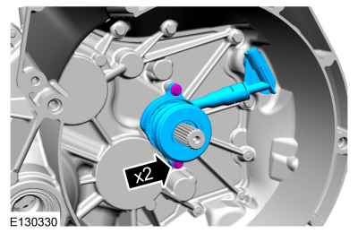
Install the selector mechanism.
-
Install the bolts.
Torque: 18 lb.ft (24 Nm)
-
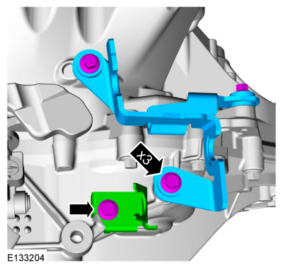
Make sure that the shift forks are in the neutral (N) position.
 |
-
Install the shift cable brackets and the bolts.
Torque: 18 lb.ft (24 Nm)
 |
-
-
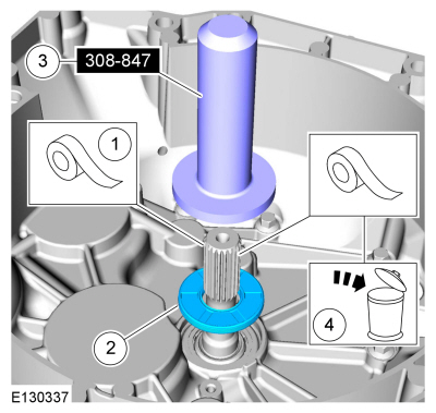
NOTICE: Use adhesive tape to cover the input shaft splines to prevent damage to the input shaft seal.
Tape the input shaft.
Use the General Equipment: Adhesive Tape
-
NOTE: Make sure that a new component is installed.
Position a new seal on the input shaft.
-
Using the special tool, install the input shaft seal.
Use Special Service Tool: 308-847 Installer, Inputshaft Seal.
-
Remove and discard the tape.
-
 |
-
-
Install new bolts.
Torque:
Stage 1: 159 lb.in (18 Nm)
Stage 2: 90°
-
Position a new LH halfshaft seal in the transmission.
-
Using the special tool, install the LH halfshaft seal.
Use Special Service Tool: 308-880 Installer, Driveshaft Seal.
- Remove Special Service Tool: 307-003 (T57L-500-B) Holding Fixture, Transmission.
-
Install new bolts.
 |
-
Install the slave cylinder and the 2 bolts.
Torque: 89 lb.in (10 Nm)
 |
-
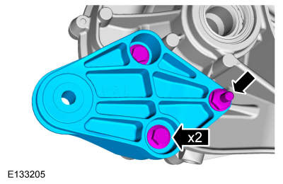
Install the roll restrictor bracket.
Torque: 35 lb.ft (48 Nm)
 |

 Transmission. Installation
Special Tool(s) /
General Equipment
205-115A
(205-115)
Installer, Drive Pinion Seal
Transmission Jack
Retaining Strap
Wooden Block
Materials
Name
Specification
Motorcraft® High Temperature 4x4 Front Axle and Wheel Bearing GreaseXG-11
WSS-M1C267-A1
Apply a thin coating of grease on the input shaft...
Other information:
Ford Fiesta 2014 - 2019 Service Manual: Ignition Coil-On-Plug. Removal and Installation
Removal NOTE: Removal steps in this procedure may contain installation details. Remove the engine appearance cover. Disconnect the crank case ventilation tube quick release coupling...
Ford Fiesta 2014 - 2019 Service Manual: Pinpoint Test - DTC: M. Diagnosis and Testing
B00C5:11, B00C5:12, B00C5:13 and B00C5:1D Refer to Wiring Diagrams Cell 46 for schematic and connector information. Normal Operation and Fault Conditions The RCM monitors the passenger seat position sensor circuits for the following faults: Open circuit Short to voltage Short to ground Current out of range Faulted passenger se..
Categories
- Manuals Home
- Ford Fiesta Service Manual (2014 - 2019)
- General Information
- Clutch - 6-Speed Manual Transmission – B6
- Engine - 1.6L EcoBoost (132kW/180PS) – Sigma
- Maintenance Schedules - Gasoline Engines. Description and Operation
- Timing Belt. Removal and Installation
Rear Wheel Speed Sensor. Removal and Installation
Removal
NOTE: Removal steps in this procedure may contain installation details.
Remove the retainer and pull the rear splash shield outward. Disconnect the electrical connector and detach the wiring retainer.