Ford Fiesta: Engine Ignition - 1.6L EcoBoost (132kW/180PS) – Sigma / Ignition Coil-On-Plug. Removal and Installation
Removal
NOTE: Removal steps in this procedure may contain installation details.
-
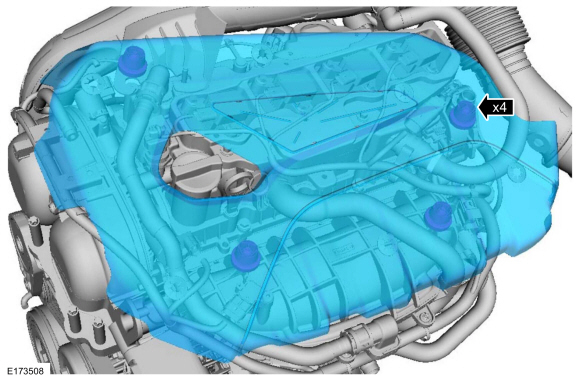
Remove the engine appearance cover.
 |
-
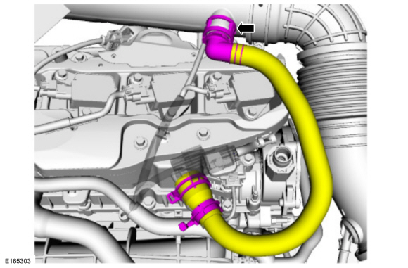
Disconnect the crank case ventilation tube quick release coupling.
Refer to: Quick Release Coupling (310-00B Fuel System - General Information - 1.6L EcoBoost (132kW/180PS) – Sigma, General Procedures).
 |
-
NOTE: Use compressed air to remove any foreign material from the ignition coil-on-plugs and surrounding area before removing the ignition coil-on-plugs.
NOTE: When removing the ignition coil-on-plugs, a slight twisting motion will break the seal and ease removal.
NOTE: When installing the ignition coil-on-plugs, apply a small amount of silicone brake caliper grease and dielectric compound to the inside of the ignition coil-on-plug boots before installation.
-
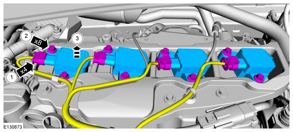
NOTE: If equipped with a sliding cover over the locking tab, then slide the cover back to gain access to the tab.
Depress the locking tab on the ignition coil-on-plug electrical connector, and disconnect the electrical connector from the ignition coil-on-plug.
-
Remove the ignition coil-on-plug retainers.
Torque: 89 lb.in (10 Nm)
-
Remove the ignition coil-on-plugs.
-
 |
-
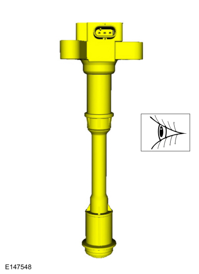
Inspect the ignition coil-on-plug assemblies. Replace
any ignition coil-on-plug assemblies with cracks, rips, or tears.
 |
Installation
-
To install, reverse the removal procedure.
 Engine Ignition. Diagnosis and Testing
General Equipment
Ford diagnostic equipment
Diagnostics
in this manual assume a certain skill level and knowledge of
Ford-specific diagnostic practices...
 Spark Plugs. Removal and Installation
Removal
NOTE:
Removal steps in this procedure may contain installation details.
Refer to: Ignition Coil-On-Plug (303-07B Engine Ignition - 1...
Other information:
Ford Fiesta 2014 - 2019 Service Manual: Accessory Drive - Component Location. Description and Operation
Item Description 1 Accessory drive belt tensioner 2 Water pump pulley 3 Crankshaft belt pulley 4 Pulley - A/C compressor 5 Drive belt idler pulley assembly 6 Generator pulley 7 Accessory drive belt ..
Ford Fiesta 2014 - 2019 Service Manual: Gasoline and Gasoline-Ethanol Fuel Systems Health and Safety Precautions. Description and Operation
WARNING: Before working on or disconnecting any of the fuel tubes or fuel system components, relieve the fuel system pressure to prevent accidental spraying of fuel. Fuel in the fuel system remains under high pressure, even when the engine is not running. Failure to follow this instruction may result in serious personal injury. WARNING: Do not smoke, carry ..
Categories
- Manuals Home
- Ford Fiesta Service Manual (2014 - 2019)
- Front Subframe. Removal and Installation
- Engine Component View. Description and Operation
- Valve Clearance Adjustment. General Procedures
- Engine Cooling - 1.6L EcoBoost (132kW/180PS) – Sigma
- Manual Transmission, Clutch, Transfer Case and Power Transfer Unit
Component Bleeding. General Procedures
Special Tool(s) / General Equipment
Master Cylinder Bleeding SetBleeding
NOTICE: If the fluid is spilled on the paintwork, the affected area must be immediately washed down with cold water.
Master Cylinder
NOTE: When a new brake master cylinder has been installed, it should be primed to prevent air from entering the system.
NOTE: Make sure the area around the master cylinder cap is clean and free of foreign material.
Remove the brake fluid reservoir cap.