Ford Fiesta: Power Steering / Tie Rod. Removal and Installation
Special Tool(s) / General Equipment
| Tie Rod End Remover | |
| Tie Rod Remover and Installer | |
| Boot Clamp Pliers |
Materials
| Name | Specification |
|---|---|
| Motorcraft® Premium Long-Life Grease XG-1-E1 |
ESA-M1C75-B |
Removal
NOTICE: When servicing inner tie rods, install a new bellows boot and clamps. The boots and clamps are designed to provide an airtight seal and protect the internal components of the steering gear. If the seal is not airtight, the vacuum generated during turning will draw water and contamination into the gear, causing failure of the steering gear components. Tie straps must not be used as they do not provide an airtight seal.
NOTICE: The inner ball joint grease is not compatible with water contamination. Do not allow water to become trapped in the grease or degradation and failure of the joint may occur.
NOTE: If the RH inner tie rod is being serviced, remove the LH outer tie rod end and bellows boot to access and hold the steering rack when loosening and tightening the inner tie rod.
NOTE: Removal steps in this procedure may contain installation details.
-
Remove the wheel and tire.
Refer to: Wheel and Tire (204-04A Wheels and Tires, Removal and Installation).
-
NOTICE: Do not use a hammer to separate the outer tie-rod end from the wheel knuckle or damage to the wheel knuckle may result.
NOTICE: Use care when installing the tie rod end remover or damage to the outer tie-rod end boot may occur.
NOTE: Count and record the number of turns required to remove the outer tie-rod end for reference during installation.
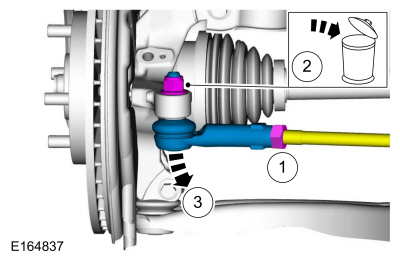
-
Loosen the tie rod end jam nut.
Torque: 46 lb.ft (63 Nm)
-
Remove and discard the outer tie rod end nut.
Torque: 39 lb.ft (53 Nm)
-
Remove the tie-rod end.
Use the General Equipment: Tie Rod End Remover
-
Loosen the tie rod end jam nut.
 |
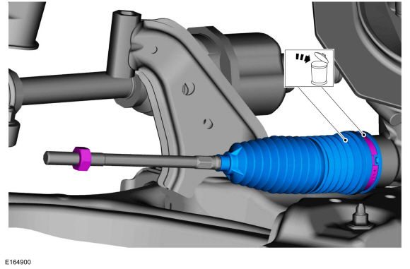
-
NOTE: Make sure the steering gear bellows is positioned correctly over the steering gear housing bead and the grooves in the inner tie-rod casting during installation.
Remove and discard the clamp and the steering gear bellows boot.
Use the General Equipment: Boot Clamp Pliers
 |
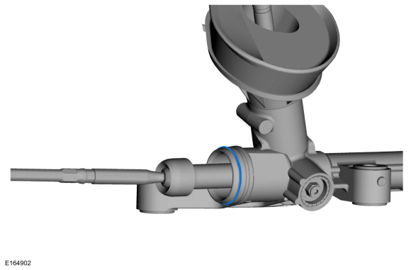
-
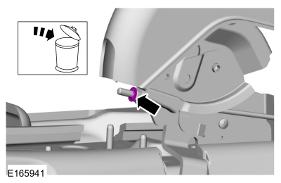
Remove the O-ring seal.
 |
-
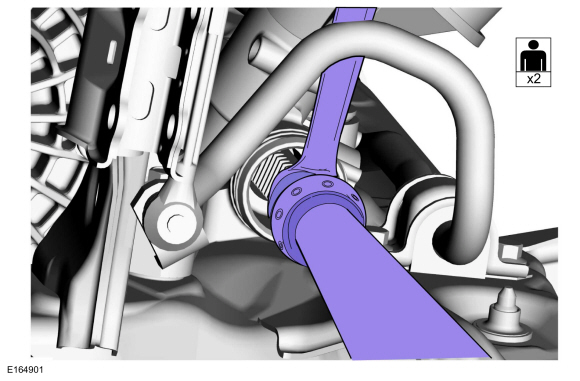
NOTICE: Place the steering gear at the center position and hold the steering gear rack while loosening or tightening the inner tie rod. Use an appropriate-sized wrench on the flat/teeth of the rack to resist rotation and to prevent damage during removal of the inner tie rod.
NOTE: Set screw style tie-rod remover and installer tool shown.
Remove the tie rod.
Use the General Equipment: Tie Rod Remover and Installer
Torque: 61 lb.ft (83 Nm)
 |
Installation
-
To install, reverse the removal procedure.
-
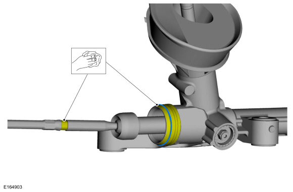
NOTICE: Thoroughly remove any abrasive material or damage to the steering gear can result.
NOTE: Clean gear before installing the new O-ring.
Clean the specified area. And install the O-ring seal provided with the bellows boot kit.
 |
-
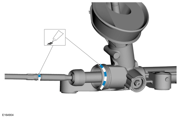
Apply the specified grease to the steering
gear-to-bellows boot mating surface and bellows boot groove on the inner
tie-rod.
Material: Motorcraft® Premium Long-Life Grease / XG-1-E1 (ESA-M1C75-B)
 |
-
Check and if necessary, adjust front toe.
Refer to: Front Toe Adjustment (204-00 Suspension System - General Information, General Procedures).
 Steering Gear. Removal and Installation
Removal
NOTE:
Removal steps in this procedure may contain installation details.
Remove the front subframe.
Refer to: Front Subframe (502-00 Uni-Body, Subframe and Mounting System, Removal and Installation)...

Other information:
Ford Fiesta 2014 - 2019 Service Manual: Radio Frequency (RF) Receiver. Removal and Installation
Special Tool(s) / General Equipment Interior Trim Remover Materials Name Specification 3M™ Super-Fast Repair Adhesive04747 - Removal Remove the headliner. Refer to: Headliner - 5-Door (501-05 Interior Trim and Ornamentation, Removal and Installation). Refer to: Headliner - 4-Door (501-05 Interior Trim and Ornamentation, Removal ..
Ford Fiesta 2014 - 2019 Service Manual: Pinpoint Test - DTC: DD. Diagnosis and Testing
U0253:00 Normal Operation and Fault Conditions The RCM uses information contained in messages from the APIM sent on the HS-CAN . DTC Fault Trigger Conditions DTC Description Fault Trigger Conditions U0253:00 Lost Communication with Accessory Protocol Interface M..
Categories
- Manuals Home
- Ford Fiesta Service Manual (2014 - 2019)
- Fuel Rail. Removal and Installation
- Service Information
- Front Subframe. Removal and Installation
- Maintenance Schedules - Gasoline Engines. Description and Operation
- Engine
Parking Brake Control. Removal and Installation
Removal
NOTE: Removal steps in this procedure may contain installation details.
Remove the floor console.Refer to: Floor Console (501-12 Instrument Panel and Console, Removal and Installation).
Remove the driver seat.
Refer to: Front Seat (501-10 Seating, Removal and Installation).
Remove the parking brake cable adjustment lock nut.
 Loosen the parking brake cable adjustment nut.