Ford Fiesta: Information and Entertainment System - General Information - Vehicles With: AM/FM/CD/SYNC/Touchscreen Display / SYNC Module [APIM] to Universal Serial Bus (USB) Port Cable. Removal and Installation
Removal
NOTE: Removal steps in this procedure may contain installation details.
NOTE: The instrument panel and floor console USB cables are taped into the wiring harness. Because the USB cables cannot be removed from the harness, this procedure applies to replacement of the cables only.
Instrument panel USB cable
-
Remove the FDIM .
Refer to: Front Display Interface Module (FDIM) (415-00B Information and Entertainment System - General Information - Vehicles With: AM/FM/CD/SYNC/Touchscreen Display, Removal and Installation).
-
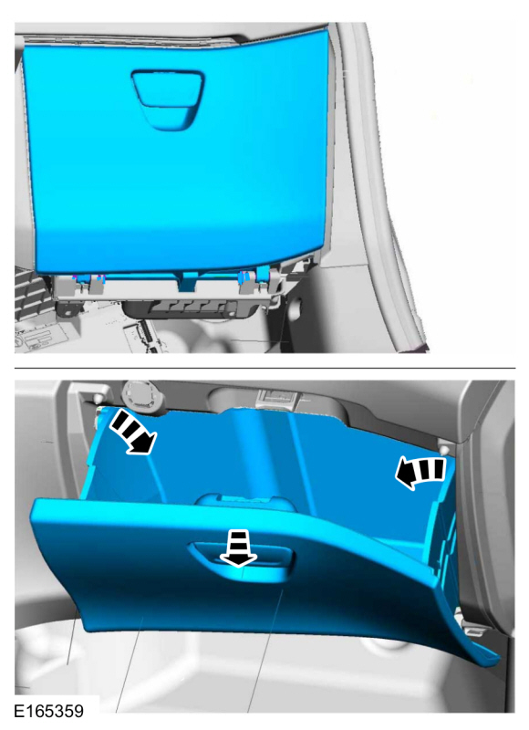
Release the retainers and remove the bracket.
 |
-
Open the glove compartment door and remove the glove compartment.
 |
-
Remove the floor console RH side trim panel.
-
Remove the screw.
-
Release the clips.
-
Remove the screw.
 |
Floor console USB cable
-
Remove the front floor console.
Refer to: Floor Console (501-12 Instrument Panel and Console, Removal and Installation).
Installation
Instrument panel USB cable
-
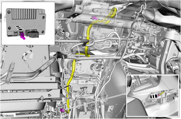
NOTE: For cable routing, view shown from the cowl behind the in-vehicle cross beam.
-
Overlay the new USB cable following the routing shown.
-
Secure the new USB cable to the wiring harness with tape or zip ties as necessary.
-
Cut both ends off the original USB cable.
-
Overlay the new USB cable following the routing shown.
 |
Floor console USB cable
-
NOTE: For cable routing, view shown with floor console installed in vehicle.
-
Overlay the new USB cable following the routing shown.
-
Secure the new USB cable to the wiring harness with tape or zip ties as necessary.
-
Cut both ends off the original USB cable.
-
Overlay the new USB cable following the routing shown.
 |
 SYNC Module [APIM] to Front Display Interface Module (FDIM) Cable. Removal and Installation
Removal
Remove the FDIM .
Refer to: Front Display Interface Module (FDIM)
(415-00B Information and Entertainment System - General Information -
Vehicles With: AM/FM/CD/SYNC/Touchscreen Display, Removal and
Installation)...
 Universal Serial Bus (USB) Hub. Removal and Installation
Removal
Open the floor console armrest.
Remove the media hub.
Disconnect the electrical connectors...
Other information:
Ford Fiesta 2014 - 2019 Service Manual: Brake Shoes. Removal and Installation
Special Tool(s) / General Equipment Flat Headed Screw Driver Materials Name Specification Motorcraft® Silicone Brake Caliper Grease and Dielectric CompoundXG-3-A ESA-M1C200-AESE-M1C171-A Removal NOTE: Removal steps in this procedure may contain installation details...
Ford Fiesta 2014 - 2019 Service Manual: Air Cleaner Outlet Pipe. Removal and Installation
Removal NOTE: Removal steps in this procedure may contain installation details. Disconnect and position aside the vent tube. Loosen the clamps and remove the air cleaner outlet pipe. Torque: 44 lb.in (5 Nm) Installation To install, reverse the removal procedure...
Categories
- Manuals Home
- Ford Fiesta Service Manual (2014 - 2019)
- Transmission Fluid Level Check. General Procedures
- Engine System - General Information
- Body Control Module (BCM). Removal and Installation
- Clutch - 6-Speed Manual Transmission – B6
- Engine
Brake Drum. Removal and Installation
Removal
NOTE: Removal steps in this procedure may contain installation details.
 WARNING:
Before beginning any service procedure in this
manual, refer to health and safety warnings in section 100-00 General
Information. Failure to follow this instruction may result in serious
personal injury.
WARNING:
Before beginning any service procedure in this
manual, refer to health and safety warnings in section 100-00 General
Information. Failure to follow this instruction may result in serious
personal injury.
Remove the wheel and tire.
Refer to: Wheel and Tire (204-04A Wheels and Tires, Removal and Installation).