Ford Fiesta: Seating / Rear Seat Backrest Cover. Removal and Installation
Special Tool(s) / General Equipment
| Flat Headed Screw Driver | |
| Hog Ring Plier |
Removal
NOTE: 60 percent seat shown, 40 percent seat similar.
NOTE: Removal steps in this procedure may contain installation details.
-
Remove the rear seat backrest.
Refer to: Rear Seat Backrest (501-10 Seating, Removal and Installation).
-
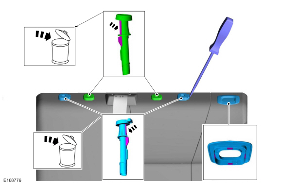
Depress the locking tabs and remove the head restraints.
 |
-
-
Release the head restraint guide sleeves locking tabs.
Use the General Equipment: Flat Headed Screw Driver
-
Remove and discard the head restraint guide sleeves.
-
Remove the child safety seat tether anchor bezel.
-
Release the head restraint guide sleeves locking tabs.
 |
-
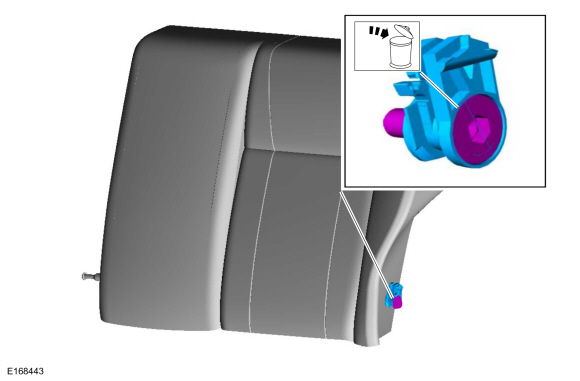
Remove the bolt and the rear seat backrest hinge assembly.
Torque: 26 lb.ft (35 Nm)
 |
-
NOTE: 5-door only.
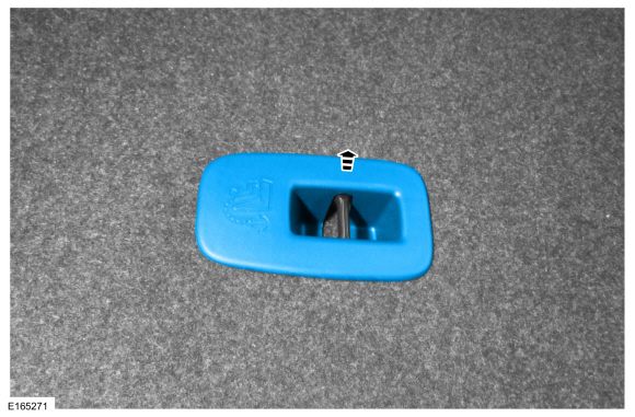
Remove the child safety seat tether anchor cover.
 |
-
NOTE: 5-door shown, 4-door similar.
Release the J-clip, unzip and position the backrest cover upward.
 |
-
NOTE: 5-door shown, 4-door similar.
-
Remove the center safety belt buckle bolt and discard the clip.
-
Route the center safety belt through the guide.
-
Remove the center safety belt buckle bolt and discard the clip.
 |
Installation
-
To install, reverse the removal procedure.
Use the General Equipment: Hog Ring Plier
-
NOTICE: Always install new head restraint guide sleeves. Difficult adjustment of the head restraint may occur. Failure to follow these instructions may result in component failure.
NOTICE: The head restraint guide sleeves are not interchangeable. Failure to install the correct head restraint guide sleeves at the correct position may result in component failure.
On both sides. Allow the head restraint guide sleeve to slide freely through the backrest foam pad and backrest cover, twist the head restraint guide sleeve while pushing it into the backrest frame hole as far as it will go, using hand pressure.
 |
 Rear Seat Cushion. Removal and Installation
Removal
Release the front locking tabs and remove the rear seat cushion.
Installation
NOTE:
Before installation, make sure the safety belts and buckles are accessible to the occupants...
 Rear Seat Backrest Latch. Removal and Installation
Removal
NOTE:
60 percent shown, 40 percent similar.
NOTE:
Removal steps in this procedure may contain installation details.
Remove the rear seat backrest...
Other information:
Ford Fiesta 2014 - 2019 Service Manual: Exterior Front Door Handle Reinforcement. Removal and Installation
Removal NOTE: LH side shown, RH side similar. Remove the front door latch. Refer to: Front Door Latch (501-14 Handles, Locks, Latches and Entry Systems, Removal and Installation). NOTE: This step is only necessary when installing a new component...
Ford Fiesta 2014 - 2019 Service Manual: Battery Drain Check. General Procedures
Check NOTE: No factory-equipped vehicle should have more than a 25 mA (0.025 amp) – 50 mA (0.050) draw depending on the vehicle's accessories. Check for current drains on the battery in excess of 25 mA (0.025 amp) – 50 mA (0.050) with all the electrical accessories off and the vehicle at rest for at least 40 minutes...
Categories
- Manuals Home
- Ford Fiesta Service Manual (2014 - 2019)
- Engine
- Manual Transmission, Clutch, Transfer Case and Power Transfer Unit
- Fuel Rail. Removal and Installation
- Manual Transmission - 6-Speed Manual Transmission – B6
- Camshafts. Removal and Installation
Wheels and Tires. Diagnosis and Testing
Preliminary Inspection
Verify the customer concern by carrying out a road test on a smooth road. If any vibrations are apparent, Refer to the Symptom Chart: NVH.To maximize tire performance, inspect for signs of incorrect inflation and uneven wear, which may indicate a need for balancing, rotation or front suspension alignment.
Correct tire pressure and driving techniques have an important influence on tire life. Heavy cornering, excessively rapid acceleration and unnecessary sharp braking increase tire wear.
Correct tire pressure and driving techniques have an important influence on tire life. Heavy cornering, exce
