Ford Fiesta: Interior Trim and Ornamentation / Rear Door Trim Panel. Removal and Installation
Ford Fiesta 2014 - 2019 Service Manual / Body and Paint / Interior Trim and Ornamentation / Rear Door Trim Panel. Removal and Installation
Special Tool(s) / General Equipment
| Pick Hook | |
| Interior Trim Remover |
Removal
-
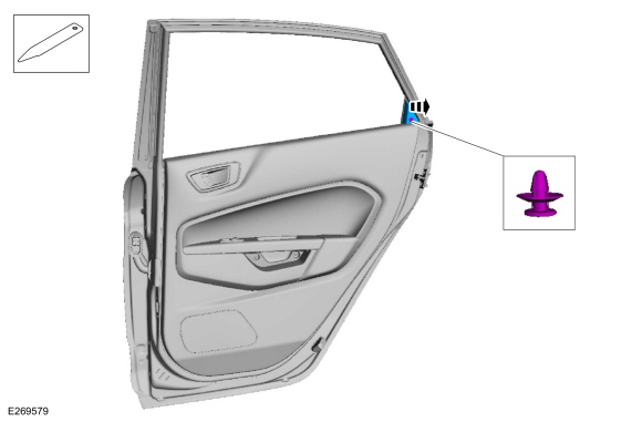
Release the clip and remove the rear door sail panel.
Use the General Equipment: Interior Trim Remover
 |
-
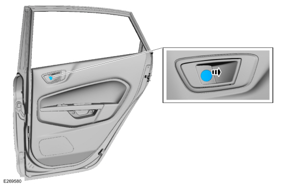
Remove the interior door handle screw cover.
Use the General Equipment: Pick Hook
 |
-
Remove the rear door trim panel screws.
 |
Vehicles with manual windows
-
Remove the window regulator handle.
-
Remove the retaining clip.
-
Remove the window regulator handle and the spacer.
-
Remove the retaining clip.
 |
All vehicles
-
Release the rear door trim panel clips in the following sequence.
-
Release the lower RH rear door trim panel clip.
Use the General Equipment: Interior Trim Remover
-
Release the lower LH rear door trim panel clip.
Use the General Equipment: Interior Trim Remover
-
Release the RH middle rear door trim panel clip.
Use the General Equipment: Interior Trim Remover
-
Release the LH middle rear door trim clip.
Use the General Equipment: Interior Trim Remover
-
Release the RH rear door trim panel clip.
Use the General Equipment: Interior Trim Remover
-
Release the LH upper rear door trim panel clip.
Use the General Equipment: Interior Trim Remover
-
Release the RH upper rear door trim panel clip.
Use the General Equipment: Interior Trim Remover
-
Release the lower RH rear door trim panel clip.
 |
-
Remove the rear door trim panel.
-
Lift upward and outward on the rear door trim panel.
-
Release the tab and disconnect the rear door latch cable.
-
If equipped.
Disconnect the rear door window control switch electrical connector.
-
Lift upward and outward on the rear door trim panel.
 |
Installation
-
To install, reverse the removal procedure
 A-Pillar Trim Panel. Removal and Installation
Removal
NOTE:
Removal steps in this procedure may contain installation details.
NOTE:
LH shown, RH similar.
Position the front door weatherstrip aside...
 Liftgate Trim Panel. Removal and Installation
Removal
NOTE:
Removal steps in this procedure may contain installation details.
Release the clips and remove the LH upper side trim panel...
Other information:
Ford Fiesta 2014 - 2019 Service Manual: Radio Frequency (RF) Receiver. Removal and Installation
Special Tool(s) / General Equipment Interior Trim Remover Materials Name Specification 3M™ Super-Fast Repair Adhesive04747 - Removal Remove the headliner. Refer to: Headliner - 5-Door (501-05 Interior Trim and Ornamentation, Removal and Installation)...
Ford Fiesta 2014 - 2019 Service Manual: Spring Lock Couplings. General Procedures
Special Tool(s) / General Equipment 310-250Disconnect Tool, Fuel LineTKIT-2012A-FLTKIT-2012A-ROW Disconnect NOTICE: When reusing liquid or vapor tube connectors, make sure to use compressed air to remove any foreign material from the connector retaining clip area before separating from the tube or damage to the tube or connector retaining clip can occur...
Categories
- Manuals Home
- Ford Fiesta Service Manual (2014 - 2019)
- Timing Belt. Removal and Installation
- Manual Transmission, Clutch, Transfer Case and Power Transfer Unit
- Engine
- Manual Transmission - 6-Speed Manual Transmission – B6
- Service Information
Component Bleeding. General Procedures
Special Tool(s) / General Equipment
Master Cylinder Bleeding SetBleeding
NOTICE: If the fluid is spilled on the paintwork, the affected area must be immediately washed down with cold water.
Master Cylinder
NOTE: When a new brake master cylinder has been installed, it should be primed to prevent air from entering the system.
NOTE: Make sure the area around the master cylinder cap is clean and free of foreign material.
Remove the brake fluid reservoir cap.Copyright © 2025 www.fofiesta7.com