Ford Fiesta: Bumpers / Rear Bumper Cover. Removal and Installation
Ford Fiesta 2014 - 2019 Service Manual / Body and Paint / Bumpers / Rear Bumper Cover. Removal and Installation
Removal
All vehicles
NOTE: Removal steps in this procedure may contain installation details.
NOTE: 5-door shown, 4-door is similar.
-
With the vehicle in NEUTRAL, position it on a hoist.
Refer to: Jacking and Lifting - Overview (100-02 Jacking and Lifting, Description and Operation).
-
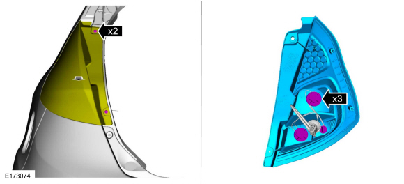
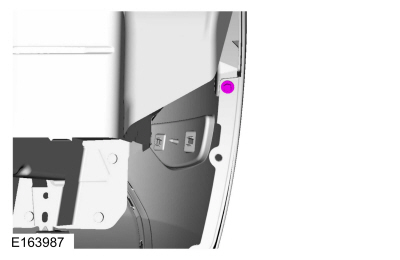
Remove the screws.
 |
4-Door
-
Remove the rear lamp assembly.
Refer to: Rear Lamp Assembly (417-01 Exterior Lighting, Removal and Installation).
5-Door
-
Remove the rear lamp assembly.
-
Remove the screws and position the rear lamp assembly.
-
Release the rear lamp assembly bulb holders.
-
Remove the screws and position the rear lamp assembly.
 |
All vehicles
-
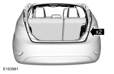
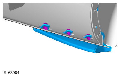
NOTE: On each side.
Remove the rear bumper cover to rear bumper cover mounting bracket pin-type retainer.
 |
-
Remove the wheel and tire.
Refer to: Wheel and Tire (204-04A Wheels and Tires, Removal and Installation).
4-Door
-
NOTE: If equipped.
NOTE: On each side.
Remove the rear mudflap pin-type retainers.
 |
-
NOTE: If equipped.
NOTE: On each side.
Release the tabs and remove the rear mudflap.
 |
-
NOTE: On each side.
Position the rear fender liner aside.
 |
5-Door
-
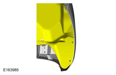
NOTE: On each side.
Remove the screws and position the rear fender liner aside.
 |
All vehicles
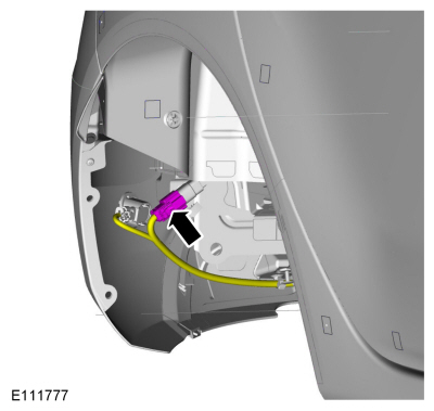
NOTE: 5-door shown, 4-door is similar.
-
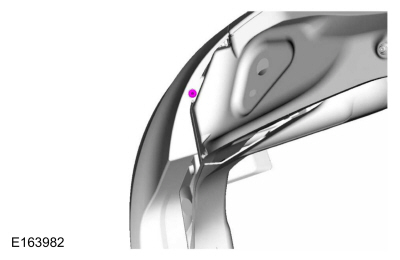
NOTE: If equipped.
Disconnect the rear bumper harness electrical connector.
 |
-
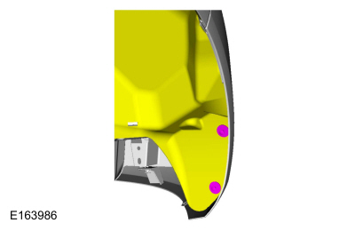
NOTE: On each side.
Remove the rear bumper cover to bumper cover bracket bolt.
 |
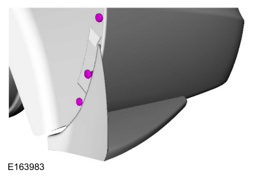
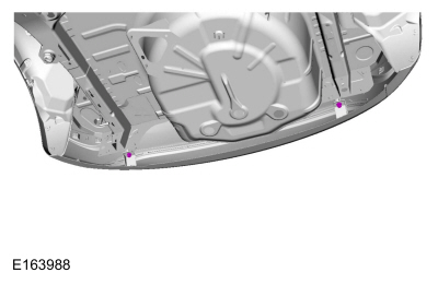
-
Remove the lower rear bumper cover pin-type retainers.
 |
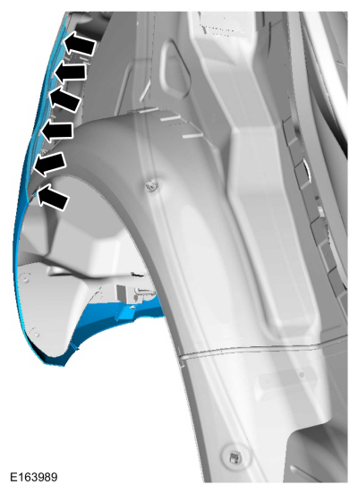
-
Release the clips on each side and remove the rear bumper cover.
 |
-
Inspect the bumper cover brackets. If required install new bumper cover brackets.
Installation
-
To install, reverse the removal procedure.
 Rear Bumper. Removal and Installation
Removal
All vehicles
NOTE:
Removal steps in this procedure may contain installation details.
Remove the rear bumper cover.
Refer to: Rear Bumper Cover (501-19 Bumpers, Removal and Installation)...
 Front Bumper Cover. Disassembly and Assembly
DISASSEMBLY
NOTE:
Disassembly steps in this procedure may contain assembly details.
Remove the front bumper cover.
Refer to: Front Bumper Cover (501-19 Bumpers, Removal and Installation)...
Other information:
Ford Fiesta 2014 - 2019 Service Manual: Cruise Control. Diagnosis and Testing
DTC Chart(s): Diagnostics in this manual assume a certain skill level and knowledge of Ford-specific diagnostic practices. REFER to: Diagnostic Methods (100-00 General Information, Description and Operation). IPC DTC Chart DTC Description Action P0565:01 Cruise Control ON Signal: General Elect..
Ford Fiesta 2014 - 2019 Service Manual: Refrigerant Identification Testing. General Procedures
Special Tool(s) / General Equipment Refrigerant Identification Equipment Activation NOTE: Use Refrigerant Identification Equipment to identify gas samples taken directly from the refrigeration system or storage containers prior to recovering or charging the refrigerant system. NOTE: Use Refrigerant Identification Equipment that conforms to SAE J1771 f..
Categories
- Manuals Home
- Ford Fiesta Service Manual (2014 - 2019)
- Manual Transmission - 6-Speed Manual Transmission – B6
- Engine Cooling - 1.6L EcoBoost (132kW/180PS) – Sigma
- Clutch - 6-Speed Manual Transmission – B6
- Engine - 1.6L EcoBoost (132kW/180PS) – Sigma
- Body Control Module (BCM). Removal and Installation
Ride Height Measurement. General Procedures
Special Tool(s) / General Equipment
Surface GaugeCheck
Ride Height Measurement - Front
NOTE: Make sure that the vehicle is positioned on a flat, level surface and the tires are inflated to the correct pressure. Vehicle should have a full tank of fuel.
Ride height = 2-3Measurement 2
Measurement 3
Use the General Equipment: Surface Gauge
Copyright © 2025 www.fofiesta7.com