Ford Fiesta: Fuel System - General Information - 1.6L EcoBoost (132kW/180PS) – Sigma / Quick Release Coupling. General Procedures
Disconnect
NOTICE: When reusing liquid or vapor tube connections, make sure to use compressed air to remove any foreign material from the connector retaining clip area before separating from the tube or damage to the tube or connector retaining clip may occur.
NOTICE: Fuel injection equipment is manufactured to very precise tolerances and fine clearances. It is essential that absolute cleanliness is observed when working with these components or component damage may occur. Always install blanking plugs to any open orifices or tubes.
NOTICE: Do not use any tools. The use of tools may cause a deformity in the clip components which may cause fuel leaks.
NOTE: Type 1
-
If servicing a liquid fuel tube quick release coupling, release the fuel system pressure.
Refer to: Fuel System Pressure Release (310-00B Fuel System - General Information - 1.6L EcoBoost (132kW/180PS) – Sigma, General Procedures).
-
Disconnect the battery ground cable.
Refer to: Battery Disconnect and Connect (414-01 Battery, Mounting and Cables, General Procedures).
-
-
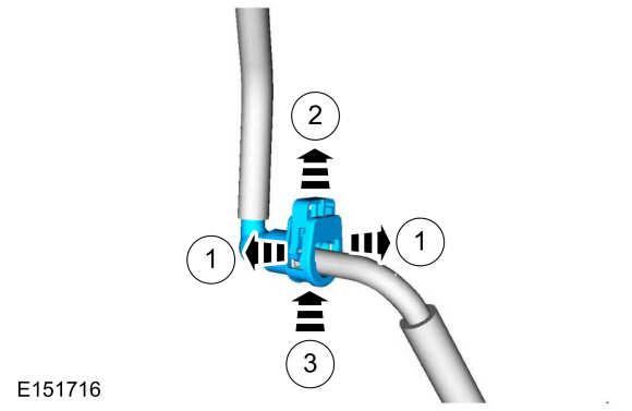
Release the locking tabs.
-
Pull up on the clip.
-
Depress the release.
-
Release the locking tabs.
 |
-
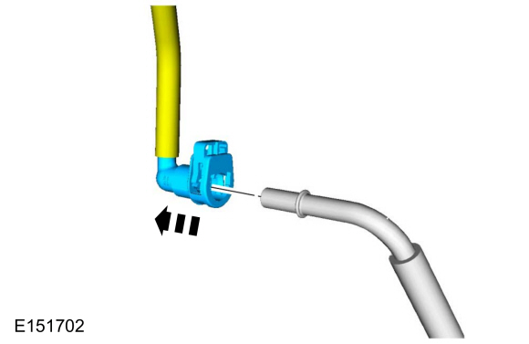
Disconnect the quick release coupling from the tube.
 |
Connect
-
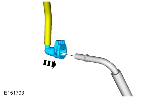
Inspect and clean both quick coupling ends.
 |
-
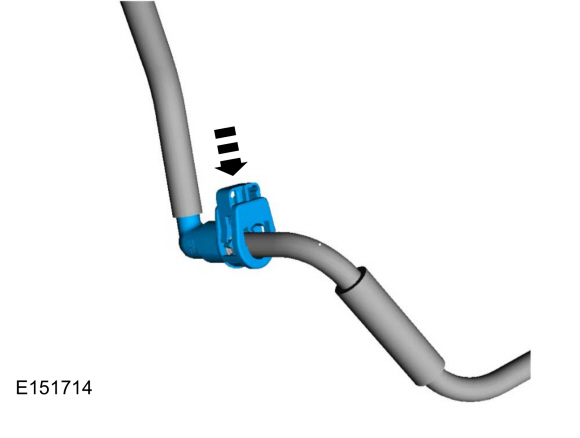
NOTE: Make sure the retainer clip is fully seated and locked onto the tube by pulling on the quick connect coupling.
Press the retainer clip into the quick connect coupling body until flush and the tabs are locked in place.
 |
-
Connect the battery ground cable.
Refer to: Battery Disconnect and Connect (414-01 Battery, Mounting and Cables, General Procedures).
Disconnect
NOTICE: When reusing liquid or vapor tube connections, make sure to use compressed air to remove any foreign material from the connector retaining clip area before separating from the tube or damage to the tube or connector retaining clip may occur.
NOTICE: Fuel injection equipment is manufactured to very precise tolerances and fine clearances. It is essential that absolute cleanliness is observed when working with these components or component damage may occur. Always install blanking plugs to any open orifices or tubes.
NOTICE: Do not use any tools. The use of tools may cause a deformity in the clip components which may cause fuel leaks.
NOTE: Type 2
-
If servicing a liquid fuel tube quick release coupling, release the fuel system pressure.
Refer to: Fuel System Pressure Release (310-00B Fuel System - General Information - 1.6L EcoBoost (132kW/180PS) – Sigma, General Procedures).
-
Disconnect the battery ground cable.
Refer to: Battery Disconnect and Connect (414-01 Battery, Mounting and Cables, General Procedures).
-
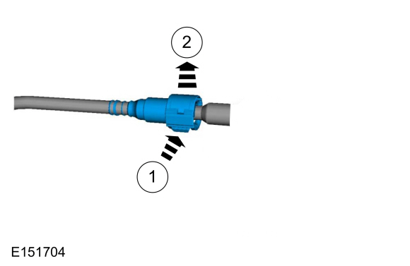
Squeeze the quick release coupling retainer locking tabs
to release the locking mechanism and push the locking mechanism outward
to release the tube.
 |
-
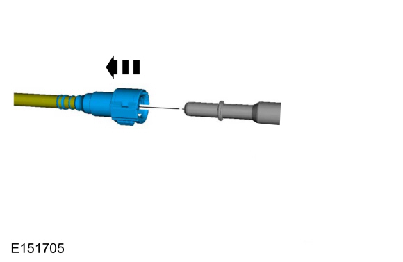
Remove the quick release coupling from the tube.
 |
Connect
-
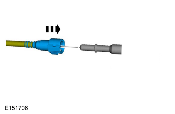
Install the quick release coupling onto the tube until fully seated.
 |
-
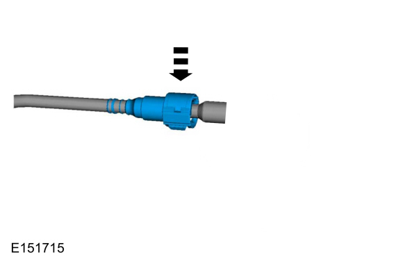
Depress the quick release coupling locking mechanism into the locked position.
 |
-
Connect the battery ground cable.
Refer to: Battery Disconnect and Connect (414-01 Battery, Mounting and Cables, General Procedures).
Disconnect
NOTICE: When reusing liquid or vapor tube connections, make sure to use compressed air to remove any foreign material from the connector retaining clip area before separating from the tube or damage to the tube or connector retaining clip may occur.
NOTICE: Fuel injection equipment is manufactured to very precise tolerances and fine clearances. It is essential that absolute cleanliness is observed when working with these components or component damage may occur. Always install blanking plugs to any open orifices or tubes.
NOTICE: Do not use any tools. The use of tools may cause a deformity in the clip components which may cause fuel leaks.
NOTE: Type 3
-
Disconnect the battery ground cable.
Refer to: Battery Disconnect and Connect (414-01 Battery, Mounting and Cables, General Procedures).
-
Release the locking tab on the quick release coupling and separate from the fitting.
 |
Connect
-
Release the locking tab and install the quick release coupling onto the fitting.
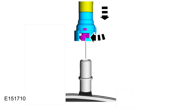 |
-
Position the locking tab into the locked position.
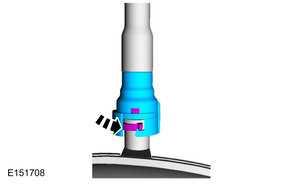 |
-
Connect the battery ground cable.
Refer to: Battery Disconnect and Connect (414-01 Battery, Mounting and Cables, General Procedures).
Disconnect
NOTICE: When reusing liquid or vapor tube connections, make sure to use compressed air to remove any foreign material from the connector retaining clip area before separating from the tube or damage to the tube or connector retaining clip may occur.
NOTICE: Fuel injection equipment is manufactured to very precise tolerances and fine clearances. It is essential that absolute cleanliness is observed when working with these components or component damage may occur. Always install blanking plugs to any open orifices or tubes.
NOTICE: Do not use any tools. The use of tools may cause a deformity in the clip components which may cause fuel leaks.
NOTE: Type 4
-
If servicing a liquid fuel tube quick release coupling, release the fuel system pressure.
Refer to: Fuel System Pressure Release (310-00B Fuel System - General Information - 1.6L EcoBoost (132kW/180PS) – Sigma, General Procedures).
-
Disconnect the battery ground cable.
Refer to: Battery Disconnect and Connect (414-01 Battery, Mounting and Cables, General Procedures).
-
Squeeze the quick release coupling retainer locking tabs
to release the locking mechanism and push the locking mechanism outward
to release the tube
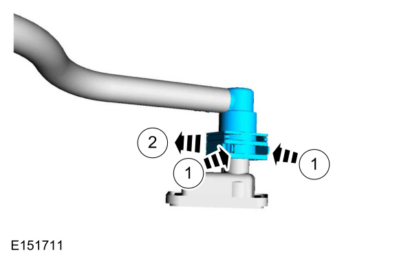 |
-
Remove the quick release coupling from the tube.
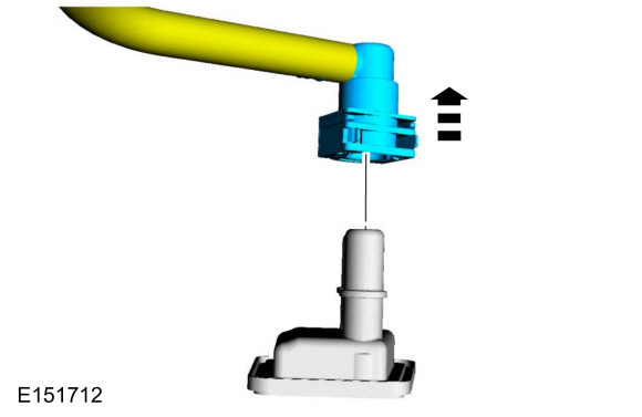 |
Connect
-
Install the quick release coupling onto the tube.
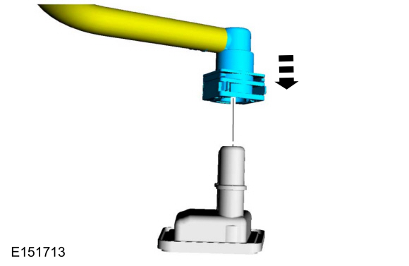 |
-
Connect the battery ground cable.
Refer to: Battery Disconnect and Connect (414-01 Battery, Mounting and Cables, General Procedures).
Disconnect
NOTICE: When reusing liquid or vapor tube connections, make sure to use compressed air to remove any foreign material from the connector retaining clip area before separating from the tube or damage to the tube or connector retaining clip may occur.
NOTICE: Fuel injection equipment is manufactured to very precise tolerances and fine clearances. It is essential that absolute cleanliness is observed when working with these components or component damage may occur. Always install blanking plugs to any open orifices or tubes.
NOTICE: Do not use any tools. The use of tools may cause a deformity in the clip components which may cause fuel leaks.
NOTE: Type 5
-
Disconnect the battery ground cable.
Refer to: Battery Disconnect and Connect (414-01 Battery, Mounting and Cables, General Procedures).
-
Release the locking tab on the quick release coupling and separate from the fitting.
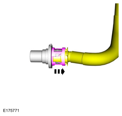 |
-
Remove the quick release coupling from the tube.
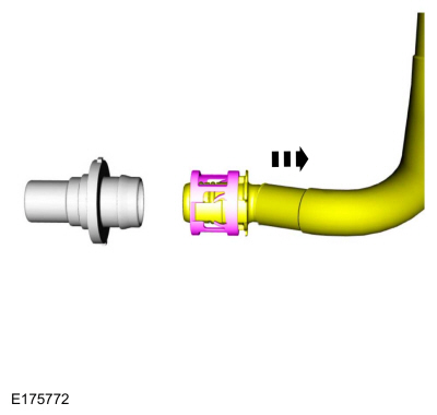 |
Connect
-
Install the quick release coupling onto the tube.
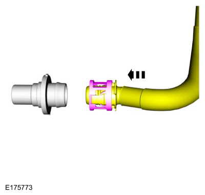 |
-
Connect the battery ground cable.
Refer to: Battery Disconnect and Connect (414-01 Battery, Mounting and Cables, General Procedures).
Disconnect
NOTICE: When reusing liquid or vapor tube connections, make sure to use compressed air to remove any foreign material from the connector retaining clip area before separating from the tube or damage to the tube or connector retaining clip may occur.
NOTICE: Fuel injection equipment is manufactured to very precise tolerances and fine clearances. It is essential that absolute cleanliness is observed when working with these components or component damage may occur. Always install blanking plugs to any open orifices or tubes.
NOTICE: Do not use any tools. The use of tools may cause a deformity in the clip components which may cause fuel leaks.
NOTE: Type 6
-
Refer to: Gasoline and Gasoline-Ethanol Fuel Systems Health and Safety Precautions (100-00 General Information, Description and Operation). WARNING:
Before beginning any service procedure in this
section, refer to Safety Warnings in section 100-00 General Information.
Failure to follow this instruction may result in serious personal
injury.
-
If servicing a liquid fuel tube quick release coupling, release the fuel system pressure.
Refer to: Fuel System Pressure Release (310-00B Fuel System - General Information - 1.6L EcoBoost (132kW/180PS) – Sigma, General Procedures).
-
Disconnect the battery ground cable.
Refer to: Battery Disconnect and Connect (414-01 Battery, Mounting and Cables, General Procedures).
-
Press both retaining tabs inward and remove quick release coupling from fuel tube.
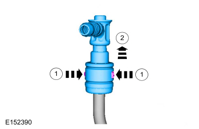 |
Connect
-
NOTE: Inspect and clean both quick release coupling ends.
Install the quick release coupling onto the tube until it is fully seated.
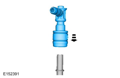 |
-
Pull on the quick release coupling to make sure it is securely fastened.
-
Connect the battery ground cable.
Refer to: Battery Disconnect and Connect (414-01 Battery, Mounting and Cables, General Procedures).
 Fuel Tank Draining. General Procedures
Special Tool(s) /
General Equipment
292-00004Fuel Tanker 100 GPM
Draining
NOTICE:
Do not remove the hose clamp at the filler neck hose
to fuel tank connection...
 Spring Lock Couplings. General Procedures
Special Tool(s) /
General Equipment
310-250Disconnect Tool, Fuel LineTKIT-2012A-FLTKIT-2012A-ROW
Disconnect
NOTICE:
When reusing liquid or vapor tube connectors, make sure to
use compressed air to remove any foreign material from the connector
retaining clip area before separating from the tube or damage to the
tube or connector retaining clip can occur...
Other information:
Ford Fiesta 2014 - 2019 Service Manual: Air Cleaner. Removal and Installation
Removal NOTE: Removal steps in this procedure may contain installation details. Disconnect the IAT sensor electrical connector. Loosen the clamp and position aside the air cleaner outlet pipe. Torque: 44 lb...
Ford Fiesta 2014 - 2019 Service Manual: Engine Cooling - System Operation and Component Description. Description and Operation
System Operation Engine coolant flows primarily from the engine to the radiator circuit and back to the coolant pump. Coolant is sent from the coolant pump through the engine block and cylinder heads. A separate circuit from the engine also feeds the heater core and turbochargers with coolant...
Categories
- Manuals Home
- Ford Fiesta Service Manual (2014 - 2019)
- Engine - 1.6L EcoBoost (132kW/180PS) – Sigma
- Clutch - 6-Speed Manual Transmission – B6
- Service Information
- Engine Cooling - 1.6L EcoBoost (132kW/180PS) – Sigma
- Timing Belt. Removal and Installation
Ride Height Measurement. General Procedures
Special Tool(s) / General Equipment
Surface GaugeCheck
Ride Height Measurement - Front
NOTE: Make sure that the vehicle is positioned on a flat, level surface and the tires are inflated to the correct pressure. Vehicle should have a full tank of fuel.
Ride height = 2-3Measurement 2
Measurement 3
Use the General Equipment: Surface Gauge
