Ford Fiesta Manuals

Ford Fiesta: Supplemental Restraint System / Pinpoint Test - DTC: N. Diagnosis and Testing

Ford Fiesta 2014 - 2019 Service Manual / Body and Paint / Supplemental Restraint System / Pinpoint Test - DTC: N. Diagnosis and Testing

B00D5:11, B00D5:12 and B00D5:13


Refer to Wiring Diagrams Cell 46 for schematic and connector information.

Normal Operation and Fault Conditions

The RCM briefly activates the PAD indicator to prove-out and verify correct functional operation of the PAD indicator to the occupants.

The RCM monitors the PAD indicator circuits for the following faults:

  • Open circuit
  • Short to voltage
  • Short to ground
  • Faulted PAD indicator

If a fault is detected, the RCM stores DTC B00D5:11, B00D5:12 or B00D5:13 in memory and sends a message to the IPC to illuminate the airbag warning indicator.


  DTC Fault Trigger Conditions


  DTC Description Fault Trigger Conditions
B00D5:11 Driver Seatbelt Sensor: Circuit Short to Ground A fault is indicated when the RCM senses a short to ground on the PAD indicator circuit.
B00D5:12 Driver Seatbelt Sensor: Circuit Short to Battery A fault is indicated when the RCM senses a short to voltage on the PAD indicator circuit.
B00D5:13 Driver Seatbelt Sensor: Circuit Open A fault is indicated when the RCM senses an open on the PAD indicator circuit. An open on the ignition voltage supply circuit to the PAD indicator also sets this DTC .

Possible Causes

  • Wiring, terminals or connectors
  • PAD indicator
  • RCM

Visual Inspection and Diagnostic Pre-checks

  • Verify CJB fuse 4 (7.5A) is OK.

PINPOINT TEST A: B00D5:11, B00D5:12 AND B00D5:13
NOTE: Most faults are due to connector and/or wiring concerns. Carry out a thorough inspection and verification before proceeding with the pinpoint test.
NOTE: Only disconnect or reconnect SRS components when instructed to do so within a pinpoint test step. Failure to follow this instruction may result in incorrect diagnosis of the SRS .
NOTE: Always make sure the correct SRS component is being installed. Parts released for other vehicles may not be compatible even if they appear physically similar. Check the part number listed in the Ford parts catalog to make sure the correct component is being installed. If an incorrect SRS component is installed, Diagnostic Trouble Codes (DTCs) may set.
NOTE: The SRS must be fully operational and free of faults before releasing the vehicle to the customer.
A1 RETRIEVE RCM (RESTRAINTS CONTROL MODULE) DIAGNOSTIC TROUBLE CODES (DTCS)
  •   WARNING: Before beginning any service procedure in this section, refer to Safety Warnings in section 100-00 General Information. Failure to follow this instruction may result in serious personal injury.
    REFER to: Pyrotechnic Device Health and Safety Precautions (100-00 General Information, Description and Operation).
  • Ignition ON.
  • Using a diagnostic scan tool, perform RCM self-test.

Was DTC B00D5:11, B00D5:12 or B00D5:13 retrieved on-demand during self-test?
Yes This fault cannot be cleared until it is corrected and the DTC is no longer retrieved on-demand during self-test.
For DTC B00D5:11, GO to A2
For DTC B00D5:12, GO to A7
For DTC B00D5:13, GO to A4
No This is an intermittent fault when present as a Continuous Memory Diagnostic Trouble Code (CMDTC) only. GO to A10

A2 CHECK THE PAD (PASSENGER AIRBAG DEACTIVATION) INDICATOR CIRCUIT FOR A SHORT TO GROUND

NOTE: This pinpoint test step attempts to change the fault reported by the RCM by inducing a different fault condition. If the reported fault changes, this indicates the RCM is functioning correctly and is not the source of the fault.

  • Ignition OFF.   WARNING: Turn the ignition OFF and wait one minute to deplete the backup power supply. Failure to follow this instruction may result in serious personal injury or death in the event of an accidental deployment.
  • Disconnect: PAD Indicator C2286.
  • Measure:
    Click to display connectors
    Positive Lead Measurement / Action Negative Lead
      C2286-2   Ground

Is the resistance greater than 10,000 ohms?
Yes GO to A9
No GO to A3

A3 CHECK THE RCM (RESTRAINTS CONTROL MODULE) FOR LOW RESISTANCE
  • Depower the SRS .
    REFER to: Supplemental Restraint System (SRS) Depowering and Repowering (501-20B Supplemental Restraint System, General Procedures).
  • Disconnect: RCM C310A and C310B.
  • Measure:
    Click to display connectors
    Positive Lead Measurement / Action Negative Lead
      C2286-2   Ground

Is the resistance greater than 10,000 ohms?
Yes GO to A9
No REPAIR the circuit.
Refer to Wiring Diagrams Cell 5 for schematic and connector information.
GO to A11

A4 CHECK THE PAD (PASSENGER AIRBAG DEACTIVATION) INDICATOR CIRCUIT FOR AN OPEN
  • Ignition OFF.
  • Depower the SRS .
    REFER to: Supplemental Restraint System (SRS) Depowering and Repowering (501-20B Supplemental Restraint System, General Procedures).
  • Disconnect: RCM C310A and C310B.
  • Disconnect: PAD Indicator C2286.
  • Measure:
    Click to display connectors
    Positive Lead Measurement / Action Negative Lead
      C2286-2   C310A-20

Is the resistance less than 0.5 ohm?
Yes GO to A5
No REPAIR the circuit.
Refer to Wiring Diagrams Cell 5 for schematic and connector information.
GO to A11

A5 CHECK THE IGNITION CIRCUIT AT THE PAD (PASSENGER AIRBAG DEACTIVATION) INDICATOR FOR VOLTAGE
  • Repower the SRS . Do not prove out the SRS at this time.
    REFER to: Supplemental Restraint System (SRS) Depowering and Repowering (501-20B Supplemental Restraint System, General Procedures).
  • Ignition ON.
  • Measure:
    Click to display connectors
    Positive Lead Measurement / Action Negative Lead
      C2286-1   Ground

Is the voltage greater than 10 volts?
Yes GO to A6
No VERIFY CJB fuse 4 (7.5A) is OK. If OK, REPAIR the circuit. Refer to Wiring Diagrams Cell 5, Connector Repair Procedures for schematic and connector information. If not OK, REFER to the Wiring Diagrams manual to identify the possible causes of the circuit short. GO to A11

A6 CHECK THE PAD (PASSENGER AIRBAG DEACTIVATION) INDICATOR
  • Ignition OFF.
  • Connect: PAD Indicator C2286.
  • Connect a fused jumper wire:
    Click to display connectors
    Positive Lead Measurement / Action Negative Lead
      C310A-20   Ground
  • Ignition ON.
  • Monitor the PAD indicator.

Does the PAD indicator illuminate?
Yes REMOVE the fused jumper wire and GO to A9
No REMOVE the fused jumper wire, INSTALL a new PAD indicator and GO to A11

A7 CHECK THE PAD (PASSENGER AIRBAG DEACTIVATION) INDICATOR CIRCUIT FOR A SHORT TO VOLTAGE
  • Ignition OFF.
  • Depower the SRS .
    REFER to: Supplemental Restraint System (SRS) Depowering and Repowering (501-20B Supplemental Restraint System, General Procedures).
  • Disconnect: RCM C310A and C310B.
  • Disconnect: PAD Indicator C2286.
  • Repower the SRS . Do not prove out the SRS at this time.
    REFER to: Supplemental Restraint System (SRS) Depowering and Repowering (501-20B Supplemental Restraint System, General Procedures).
  • Ignition ON.
  • Measure:
    Click to display connectors
    Positive Lead Measurement / Action Negative Lead
      C2286-2   Ground

Is any voltage present?
Yes REPAIR the circuit.
Refer to Wiring Diagrams Cell 5 for schematic and connector information.
GO to A11
No GO to A8

A8 CHECK THE RCM (RESTRAINTS CONTROL MODULE)

NOTE: This pinpoint test step attempts to change the fault reported by the RCM by inducing a different fault condition. If the reported fault changes, this indicates the RCM is functioning correctly and is not the source of the fault.

  • Ignition OFF.
  • Depower the SRS .
    REFER to: Supplemental Restraint System (SRS) Depowering and Repowering (501-20B Supplemental Restraint System, General Procedures).
  • Connect: RCM C310A and C310B.
  • Repower the SRS . Do not prove out the SRS at this time.
    REFER to: Supplemental Restraint System (SRS) Depowering and Repowering (501-20B Supplemental Restraint System, General Procedures).
  • Ignition ON.
  • Using a diagnostic scan tool, perform RCM self-test.
  • DIAGNOSTIC TIP: When viewing Diagnostic Trouble Codes (DTCs) with the PAD indicator disconnected, an open circuit fault is normally retrieved.

Did the on-demand DTC change from B00D5:12 to B00D5:13?
Yes INSTALL a new PAD indicator. GO to A11
No GO to A9

A9 CONFIRM THE RCM (RESTRAINTS CONTROL MODULE) FAULT

NOTE: Make sure all SRS components and the RCM electrical connectors are connected before carrying out the self-test. If not, Diagnostic Trouble Codes (DTCs) will be recorded.

  • Ignition OFF.
  • Depower the SRS .
    REFER to: Supplemental Restraint System (SRS) Depowering and Repowering (501-20B Supplemental Restraint System, General Procedures).
  • Prior to reconnecting any previously disconnected SRS component:
    • inspect connector(s) (including any inline connectors) for pushed-out, loose or spread terminals and loose or frayed wire connections at terminals.
    • inspect wire harness for any damaged, pinched, cut or pierced wires.
    • inspect RCM C310A and C310B Connector Position Assurance (CPA) lever/lock for correct operation.
    • repair any concerns found.
      Refer to Wiring Diagrams Cell 5 for schematic and connector information.
  • Connect: PAD indicator C2286.
  • Connect: RCM C310A and C310B.
  • Repower the SRS . Do not prove out the SRS at this time.
    REFER to: Supplemental Restraint System (SRS) Depowering and Repowering (501-20B Supplemental Restraint System, General Procedures).
  • Ignition ON.
  • Using a diagnostic scan tool, perform RCM self-test.

Was the original DTC retrieved on-demand during self-test?
Yes CHECK OASIS for any applicable Technical Service Bulletins (TSBs). If a TSB exists for this concern, DISCONTINUE this test and FOLLOW TSB instructions. If no Technical Service Bulletins (TSBs) address this concern, INSTALL a new RCM .
REFER to: Restraints Control Module (RCM) (501-20B Supplemental Restraint System, Removal and Installation).
GO to A11
No In the process of diagnosing the fault, the fault condition has become intermittent. Do not install any new SRS components at this time. Install SRS components only when directed to do so in the pinpoint test. GO to A10

A10 CHECK FOR AN INTERMITTENT FAULT
  • Ignition OFF.   WARNING: Turn the ignition OFF and wait one minute to deplete the backup power supply. Failure to follow this instruction may result in serious personal injury or death in the event of an accidental deployment.
  • Connect: PAD indicator C2286.
    • Inspect connector(s) (including any inline connectors) for corrosion, loose or spread terminals and loose or frayed wire connections at terminals.
    • Inspect wire harness for any damage, pinched, cut or pierced wires.
    • Inspect RCM C310A and C310B Connector Position Assurance (CPA) lever/lock for correct operation.
    • Repair any concerns found.
      Refer to Wiring Diagrams Cell 5 for schematic and connector information.
  • Connect all previously disconnected component(s) / connector(s).
  • Ignition ON.
  • Using a diagnostic scan tool, perform RCM self-test.

Was DTC B00D5:11, B00D5:12 or B00D5:13 retrieved on-demand during self-test?
Yes This fault cannot be cleared until it is corrected and the DTC is no longer retrieved on-demand during self-test.
For DTC B00D5:11, GO to A2
For DTC B00D5:12, GO to A7
For DTC B00D5:13, GO to A4
No CHECK for causes of intermittent open, short to ground or short to voltage on the PAD indicator circuit. ATTEMPT to recreate the hard fault by flexing the wire harness and cycling the ignition frequently. ACTIVATE other systems in the same wire harness. Do not install any new SRS components at this time. Install SRS components only when directed to do so in the pinpoint test. GO to A11

A11 CHECK FOR ADDITIONAL SRS (SUPPLEMENTAL RESTRAINT SYSTEM) DIAGNOSTIC TROUBLE CODES (DTCS)
  • Ignition OFF.   WARNING: Turn the ignition OFF and wait one minute to deplete the backup power supply. Failure to follow this instruction may result in serious personal injury or death in the event of an accidental deployment.
  • Reconnect all SRS components (if previously disconnected).
  • If previously directed to depower the SRS , repower the SRS . Do not prove out the SRS at this time.
    REFER to: Supplemental Restraint System (SRS) Depowering and Repowering (501-20B Supplemental Restraint System, General Procedures).
  • Ignition ON.
  • NOTE: When selecting Restraints from the Self Test menu, DTCs are retrieved from the RCM and OCSM . Using a diagnostic scan tool, perform Restraints self-test.

Are any RCM and/or OCSM Diagnostic Trouble Codes (DTCs) retrieved on-demand during self-test?
Yes Do not clear any Diagnostic Trouble Codes (DTCs) until all Diagnostic Trouble Codes (DTCs) have been resolved. DIAGNOSE and REPAIR the RCM and/or OCSM Diagnostic Trouble Codes (DTCs).
REFER to: Airbag Supplemental Restraint System (SRS) (501-20B) .
No CLEAR Continuous Memory Diagnostic Trouble Codes (CMDTCs) from all modules. PROVE OUT the SRS . The repair is complete. RETURN the vehicle to the customer.


    Pinpoint Test - DTC: M. Diagnosis and Testing

    B..

    Pinpoint Test - DTC: O. Diagnosis and Testing

    B11D8:12 and B11D8:14 Refer to Wiring Diagrams Cell 46 for schematic and connector information. Normal Operation and Fault Conditions On vehicles equipped with a 1...

    Other information:

    Ford Fiesta 2014 - 2019 Service Manual: Microphone. Removal and Installation


    Special Tool(s) / General Equipment Interior Trim Remover Removal NOTE: If the microphone is removed from the headliner, a new microphone must be installed. Headliner Microphone Pry the microphone bezel from the headliner metal mounting bracket and remove the microphone from the headliner by grasping the microphone pigtail...

    Ford Fiesta 2014 - 2019 Service Manual: Wheel and Tire Health and Safety Precautions. Description and Operation


      WARNING: Never inflate a tire that has been run flat without first removing the tire from the wheel to inspect for damage. A damaged tire can fail during inflation. Failure to follow this instruction may result in serious personal injury...

    Categories

    Brake Backing Plate. Removal and Installation

    Removal

    NOTE: Removal steps in this procedure may contain installation details.

    Remove the brake shoes.
    Refer to: Brake Shoes (206-02 Drum Brake, Removal and Installation).
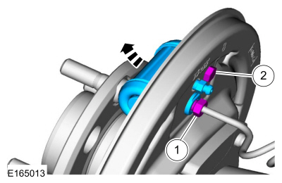
    Disconnect the brake tube fitting.
    Torque: 159 lb.in (18 Nm) Remove the bolt and wheel cylinder.
    Torque: 106 lb.in (12 Nm) Disconnect the brake shoe lever fitting and re

    read more

    Copyright © 2024 www.fofiesta7.com