Ford Fiesta: Instrument Panel and Interior Switches Illumination / Instrument Panel and Interior Switches Illumination - System Operation and Component Description. Description and Operation
System Operation
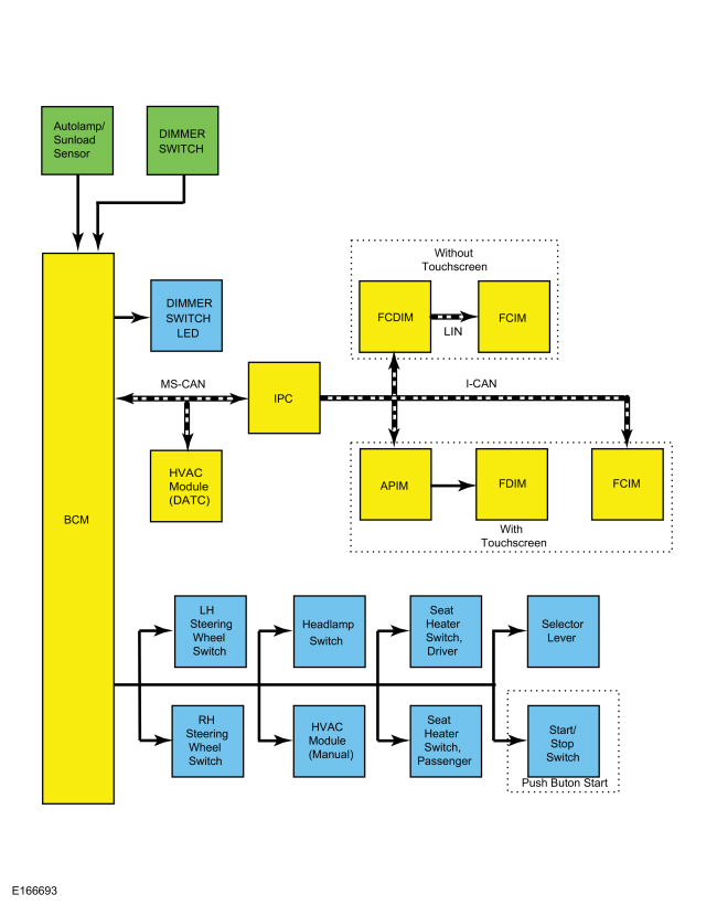
System Diagram

| Item | Description |
|---|---|
| 1 | MS-CAN |
| 2 | Infotainment Controller Area Network (I-CAN) |
| 3 | LIN |
| 4 | FCIM |
| 5 | IPC |
| 6 | APIM |
| 7 | FCDIM |
| 8 | Seat heater switch, passenger |
| 9 | Seat heater switch, driver |
| 10 | BCM |
| 11 | FCIM |
| 12 | Right steering wheel switch |
| 13 | Left steering wheel switch |
| 14 | Selector lever |
| 15 | Autolamp/Light sensor |
| 16 | HVAC Module ( EATC ) |
| 17 | FDIM |
| 18 | Dimmer switch LED |
| 19 | With touchscreen |
| 20 | Dimmer switch |
| 21 | Without touchscreen |
| 22 | Headlamp switch |
| 23 | HVAC module ( EMTC ) |
| 24 | Push button start |
| 25 | Start/Stop switch |
Network Message Chart
IPC Network Input Messages
| Broadcast Message | Originating Module | Message Purpose |
|---|---|---|
| Illumination dimming level | BCM | Used to communicate the desired illumination level based on input from the dimmer switch. |
APIM , FCIM and FCDIM Network Input Messages
| Broadcast Message | Originating Module | Message Purpose |
|---|---|---|
| Illumination dimming level | IPC | Used to command illumination level of the Infotainment Controller Area Network (I-CAN) modules. |
HVAC Module ( EATC ) Network Input Messages
| Broadcast Message | Originating Module | Message Purpose |
|---|---|---|
| Illumination dimming level | BCM | Used to command the illumination level of the HVAC module. |
Dimmable Backlighting
The dimmable backlighting is controlled by the BCM based on the ambient light level and the illumination dimmer position. When the headlamps or parking lamps are on, the BCM monitors the non-networked input from the instrument panel dimmer switch and sends a pulse-width modulated voltage to the non-networked dimmable switches and components on two circuits. The BCM supplies and controls the start/stop switch backlighting illumination on a non-network circuit independent from the other non-network dimmable components. If a fault is detected by the BCM on a dimmable illumination output circuit, the BCM sets a DTC and disables the circuit function until the fault is cleared and an ignition cycle takes place.
The BCM also sends a message over the MS-CAN to the HVAC ( EATC ) and to the IPC to control the backlighting intensity level. The IPC sends the illumination dimming level message to the APIM , FCIM (touchscreen only) and FCDIM on the Infotainment Controller Area Network (I-CAN) based on the input received from the BCM over the MS-CAN . The receiving modules use the illumination dimming level message to determine the backlighting intensity of integral illumination sources. If the receiving module does not receive the backlighting status message from the BCM or from the IPC or if the data received is deemed invalid for more than 5 seconds, the receiving module sets a missing message related DTC in continuous memory and defaults the backlighting to full nighttime intensity.
When the headlamps or parking lamps are off and the light sensor detects daytime conditions, the IPC , the FCDIM and the FDIM are illuminated to full brightness.
If the exterior lamps are activated during the daytime on vehicles equipped with autolamps, the message center illumination remains at full intensity and does not dim from the instrument panel dimmer switch during this condition. If the vehicle travels under a bridge or through a tunnel, the low level of ambient light causes the illumination level of the message center to change to the level set by the instrument panel dimmer switch. The message center illumination changes back to full intensity when the intense ambient light is restored.
If the IPC does not receive the input signals of dimming level for up to 5 seconds, the last valid received state of these signals is assumed. If the IPC receives invalid or no signals for more than 5 seconds, it assumes full night illumination level.
On vehicles not equipped with a touchscreen, the FCDIM forwards the illumination dimming level message to the FCIM via the LIN circuit.
On vehicles equipped with a touchscreen, the APIM sends the illumination dimming level message to the FDIM .
On any audio system, if the light sensor detects nighttime conditions and the parking lamps or headlamps are on, only the ON/OFF volume button and the hazard/door lock switch are illuminated on the FCIM until the audio unit is turned on. If the audio unit is on while the ignition is in the OFF position and the parking lamps or headlamps are off but the light sensor detects nighttime conditions, it is possible to control the dimming level of the FCDIM , FCIM and FDIM .
On some vehicles equipped with an ambient light sensor and FCDIM , the FCDIM provides a setup menu to select manual or automatic illumination levels based on ambient light levels. For additional information, refer to the Owner's Literature.
Non-Dimmable Backlighting
When the ignition relay (located in the CJB ) is energized, switched voltage is supplied to the window control switches.
Field-Effect Transistor (FET) Protection
Field-Effect Transistor (FET) protection protects the BCM output drivers from damage in the event that an excessive current draw is detected on a BCM output.
For a full description of Field-Effect Transistor (FET) protection,
Refer
to: Module Controlled Functions - System Operation and Component
Description (419-10 Multifunction Electronic Modules, Description and
Operation).
Component Description
Dimmer Switch
The instrument panel dimmer switch is a single detent rocker style switch with 2 inputs to the BCM to control all dimmable interior illuminated components. When the instrument panel dimmer switch is pressed up to increase the dimmable backlighting intensity or down to decrease the dimmable backlighting intensity, a ground signal is routed to the BCM . Based on the ground signal input from the instrument panel dimmer switch, the BCM sends a message over the network to the modules with dimmable backlighting, indicating the backlighting intensity level, and provides voltage to the non-networked dimmable illumination sources.
 Instrument Panel and Interior Switches Illumination - Overview. Description and Operation
Overview
Dimmable Backlighting
Dimmable
illumination provides backlighting to all buttons during day time. It
also provides backlighting to switches and control components when the
headlamps or parking lamps are on...
 Instrument Panel and Interior Switches Illumination. Diagnosis and Testing
DTC Chart: Body Control Module (BCM)
Diagnostics
in this manual assume a certain skill level and knowledge of
Ford-specific diagnostic practices...
Other information:
Ford Fiesta 2014 - 2019 Service Manual: Specifications
General Specifications Item Specification Plastic front fascia paint maximum thickness 12 mils (300 microns) Plastic rear fascia paint maximum thickness 12 mils (300 microns) General Specifications Item..
Ford Fiesta 2014 - 2019 Service Manual: Locked Seatbelt Retractor Releasing. General Procedures
Repair NOTE: If the seatbelt webbing does not extract from the seatbelt retractor from the stowed position, this may be due to a normal condition which happens when the seatbelt retracts at a high rate of speed. Follow these steps to release the seatbelt. Front row seatbelt retractor NOTE: Typical front outboard seatbelt retractor shown, other configurations similar. N..
Categories
- Manuals Home
- Ford Fiesta Service Manual (2014 - 2019)
- Timing Belt. Removal and Installation
- Manual Transmission - 6-Speed Manual Transmission – B6
- Engine. Assembly
- Engine System - General Information
- Body Control Module (BCM). Removal and Installation
Component Bleeding. General Procedures
Special Tool(s) / General Equipment
Master Cylinder Bleeding SetBleeding
NOTICE: If the fluid is spilled on the paintwork, the affected area must be immediately washed down with cold water.
Master Cylinder
NOTE: When a new brake master cylinder has been installed, it should be primed to prevent air from entering the system.
NOTE: Make sure the area around the master cylinder cap is clean and free of foreign material.
Remove the brake fluid reservoir cap.