Ford Fiesta: Front Suspension / Front Stabilizer Bar. Removal and Installation
Special Tool(s) /
General Equipment
 |
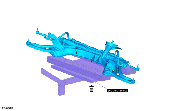
300-OTC1585AE
Powertrain Lift |
| Tie Rod End Remover |
| Wooden Block |
Removal
 WARNING:
Before beginning any service procedure in this section,
refer to Safety Warnings in section 100-00 General Information. Failure
to follow this instruction may result in serious personal injury.
WARNING:
Before beginning any service procedure in this section,
refer to Safety Warnings in section 100-00 General Information. Failure
to follow this instruction may result in serious personal injury.
-
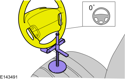
Steering wheel in straight ahead position.
-
If equipped.
Remove the tab and grommet.
-
WARNING:
Do not reuse steering column shaft bolts. This may
result in fastener failure and steering column shaft detachment or loss
of steering control. Failure to follow this instruction may result in
serious injury to vehicle occupant(s).
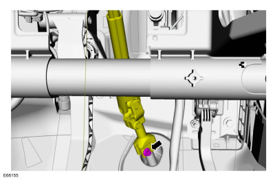
NOTICE:
Do not allow the steering column to rotate while the
steering column shaft is disconnected or damage to the clockspring may
result. If there is evidence that the steering column shaft has rotated,
remove and recenter the clockspring. For additional information, refer
to Section 501-20B.
Remove and discard the steering column shaft bolt and
disconnect the steering column shaft from the steering gear.
-
Remove the wheel and tire.
Refer to: Wheel and Tire (204-04A Wheels and Tires, Removal and Installation).
-
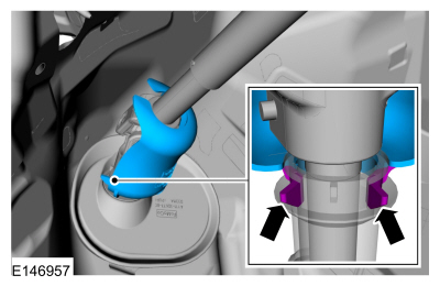
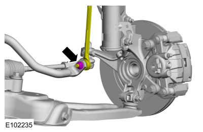
NOTE:
The stabilizer bar links are designed with low friction ball joints that have a low breakaway torque.
NOTE:
Use the hex-holding feature to prevent the ball stud
from turning while removing or installing the stabilizer bar link nut.
On both sides.
Remove and discard the from stabilizer bar link lower nuts and position aside the front stabilizer bar links.
-
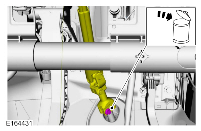
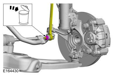
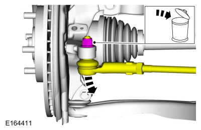
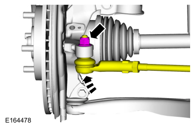
NOTICE:
Do not use a hammer to separate the outer tie-rod
end from the wheel knuckle or damage to the wheel knuckle may result.
NOTICE:
Use care when installing the tie rod separator or damage to the outer tie-rod end boot may occur.
On both sides.
Remove and discard the tie rod end nut and separate the tie rod end from the wheel knuckle.
Use the General Equipment: Tie Rod End Remover
-
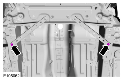
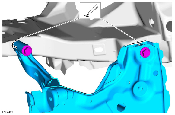
Remove the subframe brace-to-body bolts.
-
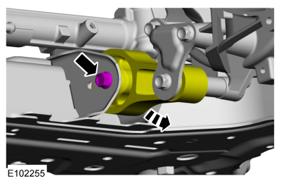
Remove the engine roll restrictor bolt.
-
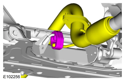
NOTE:
1.6L shown, 1.0L Fox similar.
Disconnect the exhaust isolator.
-
On both sides.
Mark the position of the subframe-to-frame mounting
location at each mounting point on the vehicle frame rails to aide in
installation.
-
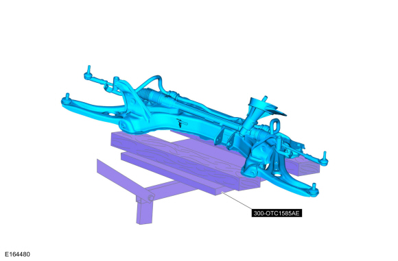
Position the Powertrain Lift.
Use Special Service Tool: 300-OTC1585AE
Powertrain Lift.
Use the General Equipment: Wooden Block
-
-
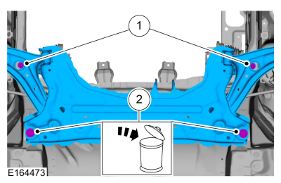
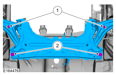
Remove the front subframe forward bolts.
-
Remove and discard the front subframe rearward bolts.
-
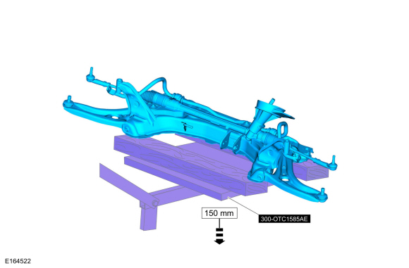
Lower the front subframe.
Use Special Service Tool: 300-OTC1585AE
Powertrain Lift.
Use the General Equipment: Wooden Block
Dimension:
5.906
in (
150
mm)
-
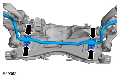
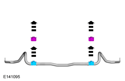
Remove the front stabilizer bar bracket bolts and the front stabilizer bar.
-
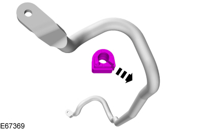
NOTE:
This step is not necessary when installing a new component.
NOTE:
Note the position of the component before removal.
Replace the front stabilizer bar bushings.
Installation
-
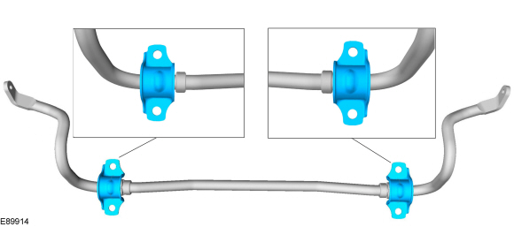
NOTICE:
The stabilizer bar bushings must be positioned
correctly with the slit in the bushing toward the rear of the vehicle or
damage to the bushings may occur.
NOTE:
This step is not necessary when installing a new component.
NOTE:
Make sure that the mating faces are clean and free of foreign material.
Make sure that these components are installed to the noted removal position.
Install the front stabilizer bar bushing.
-
NOTE:
This step is not necessary when installing a new component.
NOTE:
Make sure that the clamp is installed to the same orientation as when removed.
On both sides
Install the front stabilizer bar bushing bracket.
-
Install the new front stabilizer bar bracket bolts.
Torque:
35 lb.ft (48 Nm)
-
Raise the subframe.
Use Special Service Tool: 300-OTC1585AE
Powertrain Lift.
Use the General Equipment: Wooden Block
Dimension:
5.906
in (
150
mm)
-
-
Only tighten the bolts finger tight at this stage.
Loosely Install the front subframe forward bolts.
-
Only tighten the bolts finger tight at this stage.
Loosely Install the new front subframe rearward bolts.
-
NOTE:
If installing the subframe that was previously removed.
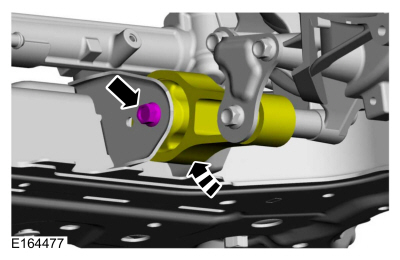
On both sides.
Align the subframe to the locating marks made during removal.
-
NOTE:
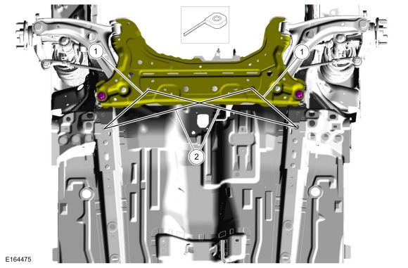
If installing a new subframe, measure for correct positioning of the subframe to vehicle underbody.
NOTE:
RH and LH dimensions are identical. All measurements on center.
Measure for correct positioning of the subframe to vehicle underbody.
-
Location 1 —
Dimension:
10.236
in (
260
mm)
-
Location 2 —
Dimension:
26.220
in (
666
mm)
-
-
Tighten the front subframe forward bolts.
Torque:
44 lb.ft (60 Nm)
-
Tighten the front subframe rearward bolts.
Torque:
Stage 1:
74 lb.ft (100 Nm)
Stage 2:
240°
-
Install the subframe brace-to-body bolts.
Torque:
35 lb.ft (48 Nm)
-
NOTE:
1.6L shown, 1.0L Fox similar.
Connect the exhaust isolator.
-
Position the engine roll restrictor and install the engine roll restrictor bolt.
Torque:
37 lb.ft (50 Nm)
-
On both sides.
Position the outer tie rods and install the new outer tie rod nuts.
Torque:
39 lb.ft (53 Nm)
-
On both sides.
Position the stabilizer bar links and install the new stabilizer bar link-to-stabilizer bar nuts.
Torque:
35 lb.ft (48 Nm)
-
Install the wheel and tire.
Refer to: Wheel and Tire (204-04A Wheels and Tires, Removal and Installation).
-
WARNING:
Do not reuse steering column shaft bolts. This may
result in fastener failure and steering column shaft detachment or loss
of steering control. Failure to follow this instruction may result in
serious injury to vehicle occupant(s).
Connect the steering column shaft and install a new steering column shaft-to-steering gear bolt.
Torque:
25 lb.ft (34 Nm)
-
If equipped.
Install the tab and grommet.
-
Check and if necessary, adjust front toe.
Refer to: Front Toe Adjustment (204-00 Suspension System - General Information, General Procedures).
Removal
NOTE:
Removal steps in this procedure may contain installation details.
NOTE:
This step is only necessary when installing a new component to the left-hand side...
Special Tool(s) /
General Equipment
204-023
(T73T-1217-A)
Installer, Wheel Hub Bearing Cup
204-180
(T93P-5493-A)
Remover/Installer, BushingTKIT-1993-FLMTKIT-1993-LMTKIT-1993-FM
205-140
(T80T-4000-F)
Installer, Drive Pinion Bearing Cup
205-153
(T80T-4000-W)
Handle
205-225
(T85T-1225-BH)
Installer, Axle Bearing CupTKIT-1985-..
Other information:
Special Tool(s) /
General Equipment
211-001
(TOOL-3290-D)
Remover, Tie-Rod End
Removal
NOTICE:
Suspension fasteners are critical parts that affect
performance of vital components and systems. Failure of these fasteners
may result in major service expense. Use the same or equivalent parts if
replacement is necessary. Do not use a replacement part of lesser
q..
Body
The body consists of the following:
Four-door sedan
Five-door hatchback
High-Strength Low Alloy (HSLA), ultra high-strength steel (UHSS) and mild steels
Roof outer panel constructed of mild steel
Steel hood
Steel luggage compartment lid
Body side outer panels constructed of mild steel
Dual-phase steel (DP) in select body struct..
Categories
Preliminary Inspection
Verify the customer concern by carrying out a road test on a
smooth road. If any vibrations are apparent, Refer to the Symptom
Chart: NVH.
To maximize tire performance, inspect for signs of incorrect
inflation and uneven wear, which may indicate a need for balancing,
rotation or front suspension alignment.
Correct tire pressure and driving techniques have an
important influence on tire life. Heavy cornering, excessively rapid
acceleration and unnecessary sharp braking increase tire wear.
Correct
tire pressure and driving techniques have an important influence on
tire life. Heavy cornering, exce
read more

 Front Strut and Spring Assembly. Removal and Installation
 Front Wheel Bearing. Removal and Installation