Ford Fiesta: Information and Entertainment System - General Information - Vehicles With: AM/FM/CD/SYNC/Touchscreen Display / Front Controls Interface Module (FCIM). Removal and Installation
Ford Fiesta 2014 - 2019 Service Manual / Information and Entertainment Systems / Information and Entertainment System - General Information - Vehicles With: AM/FM/CD/SYNC/Touchscreen Display / Front Controls Interface Module (FCIM). Removal and Installation
Special Tool(s) / General Equipment
| Interior Trim Remover |
Removal
NOTE: Removal steps in this procedure may contain installation details.
-
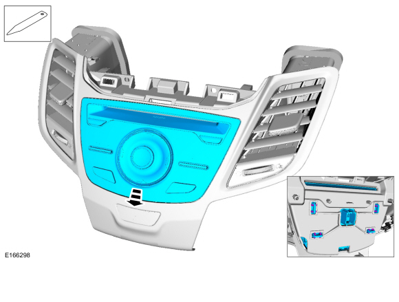
Remove the instrument panel center upper trim panel.
Refer to: Instrument Panel Center Upper Trim Panel (501-12 Instrument Panel and Console, Removal and Installation).
-
Release the clips, remove the bolts and the FCIM , media bin and center register assembly.
-
Disconnect the electrical connector.
Torque: 22 lb.in (2.5 Nm)
-
Disconnect the electrical connector.
 |
Touchscreen
-
Remove the screws and the FCIM .
Torque: 18 lb.in (2 Nm)
 |
Sony Touchscreen
-
Remove the FCIM .
Use the General Equipment: Interior Trim Remover
 |
Installation
-
To install, reverse the removal procedure.
 Audio Front Control Module (ACM). Removal and Installation
Removal
NOTE:
Removal steps in this procedure may contain installation details.
NOTE:
This step is only necessary when installing a new component...
 Front Display Interface Module (FDIM). Removal and Installation
Removal
NOTE:
Removal steps in this procedure may contain installation details.
Remove the instrument panel center upper trim panel...
Other information:
Ford Fiesta 2014 - 2019 Service Manual: A-Pillar Assembly. Removal and Installation
Special Tool(s) / General Equipment Resistance Spotwelding Equipment Hot Air Gun 8 mm Drill Bit MIG/MAG Welding Equipment Spot Weld Drill Bit Materials Name Specification Metal Bonding AdhesiveTA-1, TA-1-B, 3M™ 08115, LORD Fusor® 108B, Henkel Teroson EP 5055 - Removal WARNING: Before begi..
Ford Fiesta 2014 - 2019 Service Manual: Gearshift Cables - 6-Speed Manual Transmission – B6. Removal and Installation
Removal With the vehicle in N , position it on a hoist. Refer to: Jacking and Lifting - Overview (100-02 Jacking and Lifting, Description and Operation). Remove the battery tray. Refer to: Battery Tray - 1.6L EcoBoost (132kW/180PS) – Sigma (414-01 Battery, Mounting and Cables, Removal and Installation). Disconnect the gearshift cab..
Categories
- Manuals Home
- Ford Fiesta Service Manual (2014 - 2019)
- Cylinder Head. Removal and Installation
- Engine. Assembly
- Engine
- Manual Transmission, Clutch, Transfer Case and Power Transfer Unit
- Front Strut and Spring Assembly. Removal and Installation
Front Strut and Spring Assembly. Removal and Installation
Removal
NOTE: Removal steps in this procedure may contain installation details.
NOTE: This step is only necessary when installing a new component to the left-hand side.
Remove the nuts and position aside the remote brake fluid reservoir.Torque: 62 lb.in (7 Nm)
 Remove the strut and spring assembly upper mount nuts.
 Torque: 22 lb.ft (30 Nm)

Copyright © 2026 www.fofiesta7.com