Ford Fiesta: Evaporative Emissions - 1.6L EcoBoost (132kW/180PS) – Sigma / Evaporative Emission System Leak Test. General Procedures
Ford Fiesta 2014 - 2019 Service Manual / Engine / Evaporative Emissions - 1.6L EcoBoost (132kW/180PS) – Sigma / Evaporative Emission System Leak Test. General Procedures
Activation
-
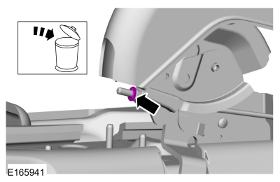
Disconnect the vapor tube-to-EVAP canister purge valve quick connect coupling (engine side).
Refer to: Quick Release Coupling (310-00B Fuel System - General Information - 1.6L EcoBoost (132kW/180PS) – Sigma, General Procedures).
-
Connect the VACUTEC Smoke Machine Fuel Evaporative Emission Tester to
the EVAP canister purge valve fitting. Refer to the manufacturer's
instructions.
-
Connect the scan tool and open the EVAP canister purge valve.
-
Using the scan tool, close the EVAP canister vent solenoid. Refer to the manufacturer's instructions.
-
Using the VACUTEC Smoke Machine Fuel Evaporative Emission Tester, pressurize the EVAP system.
-
Monitor the indicator flag on the VACUTEC Smoke Machine
Fuel Evaporative Emission Tester. If the measurement is below the
indicator flag, the system has passed the leak test and the test
procedure is complete. If the measurement is above the indicator flag,
the system has failed the leak test. If the leak test has failed,
proceed to next step.
-
Introduce smoke from the VACUTEC Smoke Machine Fuel Evaporative
Emission Tester into the EVAP system. Refer to the manufacturer's
instructions.
-
Use the halogen light provided with the VACUTEC Smoke
Machine Fuel Evaporative Emission Tester to look for smoke coming from
the EVAP system. This would indicate a leak point.
-
Repair any leaks as necessary.
-
Repeat the leak test until the system passes.
 Evaporative Emissions. Diagnosis and Testing
Engine Diagnostic Information
Diagnostics
in this manual assume a certain skill level and knowledge of
Ford-specific diagnostic practices. For information about these,REFER to: Diagnostic Methods (100-00 General Information, Description and Operation)...
 Evaporative Emission Canister. Removal and Installation
Removal
NOTE:
Removal steps in this procedure may contain installation details.
With the vehicle in NEUTRAL, position it on a hoist...
Other information:
Ford Fiesta 2014 - 2019 Service Manual: Ignition Lock Cylinder. Removal and Installation
Removal Non-functional lock cylinder NOTE: For non-functional ignition lock cylinders, replace the ingition lock cylinder housing. Replace the ingition lock cylinder housing. Refer to: Ignition Lock Cylinder Housing (211-05 Steering Wheel and Column Electrical Components, Removal and Installation)...
Ford Fiesta 2014 - 2019 Service Manual: Locks, Latches and Entry Systems. Diagnosis and Testing
DTC Chart: BCM Diagnostics in this manual assume a certain skill level and knowledge of Ford-specific diagnostic practices.REFER to: Diagnostic Methods (100-00 General Information, Description and Operation). BCM DTC Chart DTC Description Action B108F:23 Cabin Lock/Unlo..
Categories
- Manuals Home
- Ford Fiesta Service Manual (2014 - 2019)
- Engine
- Valve Cover. Removal and Installation
- Engine - 1.6L EcoBoost (132kW/180PS) – Sigma
- Jacking and Lifting - Overview. Description and Operation
- Service Information
Parking Brake Control. Removal and Installation
Removal
NOTE: Removal steps in this procedure may contain installation details.
Remove the floor console.Refer to: Floor Console (501-12 Instrument Panel and Console, Removal and Installation).
Remove the driver seat.
Refer to: Front Seat (501-10 Seating, Removal and Installation).
Remove the parking brake cable adjustment lock nut.
 Loosen the parking brake cable adjustment nut.
Copyright © 2026 www.fofiesta7.com