Ford Fiesta: Supplemental Restraint System / Driver Knee Airbag. Removal and Installation
Special Tool(s) / General Equipment
| Interior Trim Remover |
Removal
 WARNING:
The following procedure prescribes critical repair steps
required for correct restraint system operation during a crash. Follow
all notes and steps carefully. Failure to follow step instructions may
result in incorrect operation of the restraint system and increases the
risk of serious personal injury or death in a crash.
WARNING:
The following procedure prescribes critical repair steps
required for correct restraint system operation during a crash. Follow
all notes and steps carefully. Failure to follow step instructions may
result in incorrect operation of the restraint system and increases the
risk of serious personal injury or death in a crash.
NOTE: Removal steps in this procedure may contain installation details.
-
Depower the SRS .
Refer to: Supplemental Restraint System (SRS) Depowering and Repowering (501-20B Supplemental Restraint System, General Procedures).
-
Remove the stoplamp switch.
Refer to: Stoplamp Switch (417-01 Exterior Lighting, Removal and Installation).
-
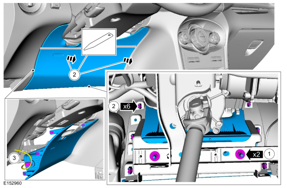
Remove the driver knee airbag.
-
Remove the nuts.
Torque: 71 lb.in (8 Nm)
-
Release the clips and separate the driver knee airbag.
Use the General Equipment: Interior Trim Remover
-
NOTICE: Do not pull the knee air bag module electrical connector out by the locking button. Damage to the locking button can occur.
NOTE: Follow the unique instructions or graphic for this step in installation.
Disconnect and remove the driver knee airbag.
-
Remove the nuts.
 |
Installation
WARNING:
Incorrect repair techniques or actions can cause an
accidental pyrotechnic device deployment. Make sure the supplemental
restraint and pedestrian protection system (if equipped) is depowered
before reconnecting the component. Refer to the depowering General
Procedure in section 501-20B. Failure to precisely follow depowering
instructions could result in serious personal injury from an accidental
deployment.
-
NOTICE: Make sure the knee air bag module electrical connector locking button is in the released position when connected. Do not install the knee air bag module electrical connector by the locking button. Failure to follow these instructions may cause connector damage.
To install, reverse the removal procedure.
-
Repower the SRS .
Refer to: Supplemental Restraint System (SRS) Depowering and Repowering (501-20B Supplemental Restraint System, General Procedures).
 Front Impact Severity Sensor. Removal and Installation
Removal
WARNING:
The following procedure prescribes critical repair steps
required for correct restraint system operation during a crash...
 Occupant Classification System (OCS) Sensor. Removal and Installation
Special Tool(s) /
General Equipment
Hog Ring Plier
Removal
WARNING:
The following procedure prescribes critical repair steps
required for correct restraint system operation during a crash...
Other information:
Ford Fiesta 2014 - 2019 Service Manual: Horn. Diagnosis and Testing
DTC Chart(s) DTC Chart: Horn Diagnostics in this manual assume a certain skill level and knowledge of Ford-specific diagnostic practices. REFER to: Diagnostic Methods (100-00 General Information, Description and Operation). Body Control Module (BCM) DTC Chart DTC Description Actions B1323:23 ..
Ford Fiesta 2014 - 2019 Service Manual: Auxiliary Climate Control. Diagnosis and Testing
DTC Chart: Heating, Ventilation And Air Conditioning (HVAC) Control Module Diagnostics in this manual assume a certain skill level and knowledge of Ford-specific diagnostic practices. For information about these practices, REFER to: Diagnostic Methods (100-00 General Information, Description and Operation). DTC Description Action ..
Categories
- Manuals Home
- Ford Fiesta Service Manual (2014 - 2019)
- Camshafts. Removal and Installation
- Maintenance Schedules
- Engine
- Engine System - General Information
- Manual Transmission - 6-Speed Manual Transmission – B6
Wheels and Tires. Diagnosis and Testing
Preliminary Inspection
Verify the customer concern by carrying out a road test on a smooth road. If any vibrations are apparent, Refer to the Symptom Chart: NVH.To maximize tire performance, inspect for signs of incorrect inflation and uneven wear, which may indicate a need for balancing, rotation or front suspension alignment.
Correct tire pressure and driving techniques have an important influence on tire life. Heavy cornering, excessively rapid acceleration and unnecessary sharp braking increase tire wear.
Correct tire pressure and driving techniques have an important influence on tire life. Heavy cornering, exce